
Loudspeaker Protector Monitors Current

The circuit in question is a thermal protection system designed for use in high-power audio amplifier applications. It primarily serves to prevent damage to the amplifier and connected loudspeakers by monitoring the temperature of a critical component, the series resistor, which experiences significant power dissipation during operation.
The power amplifier outputs a maximum of 100W into an 8Ω load, leading to a power dissipation of 1.25W across the 0.1Ω resistor. This resistor's temperature rise is directly proportional to the power being handled by the amplifier. The thermistor, which is thermally bonded to the resistor, plays a crucial role in this circuit by changing its resistance in response to temperature variations.
The LM339 quad comparator integrates four comparators, each monitoring the voltage across a resistor ladder connected to the thermistor. The adjustable threshold voltage, set by trimpot VR1, allows for calibration based on the specific characteristics of the thermistor used. As the thermistor heats up and its resistance increases, the voltage at the non-inverting inputs of the comparators rises. When this voltage exceeds the threshold set at the inverting inputs, the comparators output a high signal, activating the corresponding LED indicators.
The circuit incorporates a dual-layer safety mechanism through the use of NOR gates connected to the outputs of the third and fourth comparators. The first latch, controlled by the third comparator, engages relay 1 and the attenuation network, which consists of resistors RA and RB. This network reduces the power output of the amplifier to prevent overheating. If the temperature continues to rise, the fourth comparator will trigger the second latch, activating relay 2, which disconnects the loudspeaker load entirely, safeguarding both the amplifier and the speakers from damage.
The design of the resistor values (R1-R4) is critical and should be tailored to the specific thermistor being used. The example provided indicates that with a thermistor rated at 1.5kΩ at 25°C, the resistor values can be adjusted accordingly to ensure accurate temperature monitoring and response.
For setup, the circuit requires a sine wave oscillator connected to the input of the power amplifier, with a dummy load at the output to simulate real-world conditions. Calibration involves setting the desired power level and adjusting trimpot VR1 to ensure that LED1 illuminates, followed by testing the system under increased power conditions to confirm that all LEDs activate as expected, indicating proper functionality of the thermal protection mechanism.This circuit uses a 0. 1O 1W resistor connected in series with the output of a power amplifier. When the amplifier is delivering 100W into an 8O load, the resistor will be dissipating 1. 25W. The resulting temperature rise is sensed by a thermistor which is thermally bonded to the resistor. The thermistor is connected in series with a resistor strin g which is monitored by the non-inverting (+) inputs of four comparators in an LM339 quad comparator. All of the comparator inverting inputs are connected to an adjustable threshold voltage provided by trimpot VR1.
As the thermistor heats up, its resistance increases, raising the voltage along the resistor ladder. When the voltage on the non-inverting input of each comparator exceeds the voltage at its inverting input, the output switches high and illuminates the relevant LED. NOR gate latches are connected to the outputs of the third and fourth comparators. When the third comparator switches high, the first latch is set, turning on Q1 and relay 1. This switches in an attenuation network (resistors RA & RB) to reduce the power level. However, if the power level is still excessive, comparator 4 will switch, setting its latch and turning on Q2 and relay 2.
This disconnects the loudspeaker load. The thermistor then needs to cool down before normal operation will be restored. The values of R1-R4 depend on the thermistor used. For example, if a thermistor with a resistance of 1. 5kO at 25 °C is used, then R1 could be around 1. 5kO and R2, R3 and R4 would each be 100O (depending the temperature coefficient of the thermistor). The setup procedure involves connecting a sinewave oscillator to the input of the power amplifier and using a dummy load for the output. Set the power level desired and adjust trimpot VR1 to light LED1. Then increase the power to check that the other LEDs light at satisfactory levels. 🔗 External reference
Related Circuits
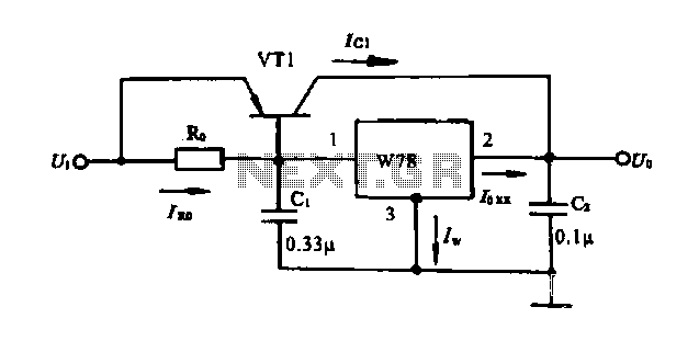
Extend the current application circuit. The maximum output current of the integrated three-terminal device in production is 1.5A. If the output current exceeds 1.5A, an external power transistor can be utilized to increase the output current, as illustrated in...
This circuitry facilitates the connection between the computer's Z RS-23 serial interface and the current ring circuitry. It converts the voltage signal of the transmission into a current signal of 20 mA, achieving a maximum speed of 1200 bits....
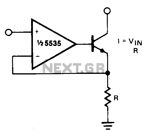
The output current is Iqut = Vin/R. For negative currents, a PNP transistor can be utilized, and for improved accuracy, a Darlington pair may be substituted for the transistor. With careful design, this circuit can be employed to control...
In this circuit, an LM339 quad voltage comparator is utilized to generate a time delay and control a high current output at low voltage. Approximately 5 amps of current can be sourced using a pair of fresh alkaline D...
This is a INA159 Dual-Polarity, Bidirectional Current-Shunt-Monitor Circuit. This circuit uses OPA340 because it has near rail-to-rail input and output swing. The INA159 is an integrated circuit designed for high precision current sensing applications. It is capable of measuring bidirectional...
Another adjustment of application operational amplifiers to adapt a power supply is apparent below. The power supply requires an additional adjustment to supply the op-amps with a bipolar voltage (+/- 8 volts), and the negative voltage is also used...