
Heartbeat Monitor Circuit

The infrared photodiode operates by converting light into an electrical signal. When the heart contracts, blood volume in the skin increases, leading to variations in IR reflectivity. The photodiode captures these variations, producing a small electrical signal that corresponds to the heartbeat.
To process this weak signal, a transistor is used as a switch or amplifier. The transistor can provide the necessary gain to elevate the signal strength, making it suitable for further processing. The operational amplifier, known for its high input impedance and low output impedance, is configured to amplify the signal from the photodiode. The op amp can be set up in a non-inverting configuration to ensure that the output signal is in phase with the input signal, further enhancing the signal quality.
The amplified signal can then be fed into logic circuitry, allowing for digital processing or triggering of other components in a system. Alternatively, the signal can be connected to an oscilloscope for visualization, enabling real-time monitoring of the heartbeat signal. This configuration is essential for applications in medical devices, fitness monitoring, and other health-related technologies where accurate heart rate detection is necessary. The design should also consider factors such as noise reduction and signal integrity to ensure reliable performance in various environments. An IR photodiode, which senses IR skin reflectivity as a result of increased blood volume during the periods that the heart forcibly contracts, is used to pick up a signal that is correlated with the heartbeat. A transistor and op amp raise this to a level suitable to trigger logic circuitry or to be displayed on a scope.
Related Circuits
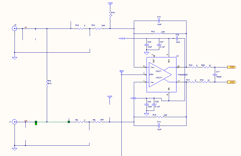
Prior to the test point, there is an AD744 operational amplifier with its output connected to a 10nF capacitor. Following this, a 1kΩ resistor connects to ground. From the junction where the capacitor and resistor meet, a 4.7kΩ resistor...
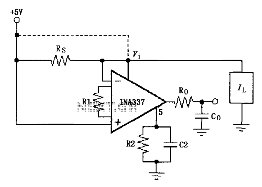
The INA337 circuit, as illustrated, is part of a load current measuring shunt circuit. It generates a voltage drop across the sampling resistor Rs, which is connected in series between the power source and the load. The load current...
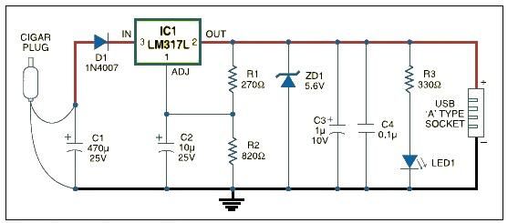
USB car charger adapter circuit design using LM317 regulator circuit The USB car charger adapter circuit utilizing the LM317 voltage regulator is designed to convert a car's 12V DC power supply into a stable 5V output, suitable for charging USB-powered...
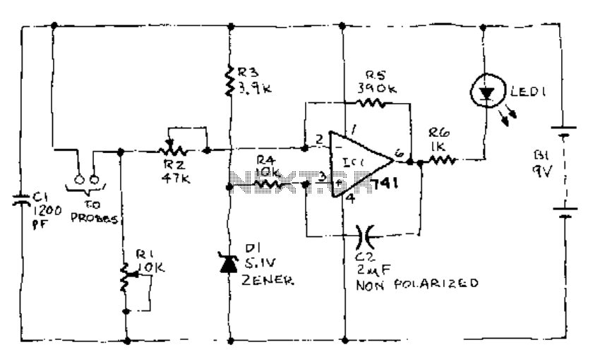
When the soil is moist, the LED glows. If the moisture falls below a certain predetermined level, the LED begins to flash. If there is still less moisture, the LED turns off. To calibrate, connect the battery and insert...
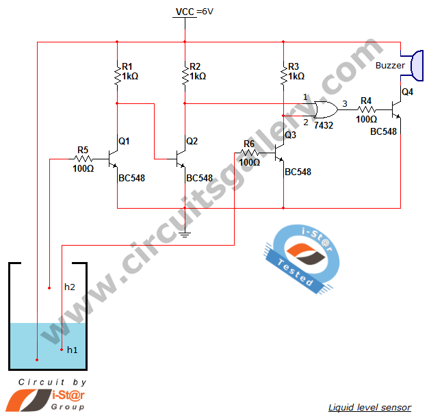
A variety of small electronic projects related to water level sensors have been posted in the Circuits Gallery. This particular project is designed for school students to detect the water level within a water tank or any other water...

This design circuit functions to filter out interference signals, ensuring that the signal received from a Morse code station is distinct. The circuit utilizes the earliest mode of radio communications, which employs Morse Code on a continuous wave carrier...