
Heat Sensor

The heat sensing circuit typically employs a temperature sensor, such as a thermistor or an LM35, which detects the ambient temperature. The output from the sensor is fed into a comparator circuit, which compares the sensor’s output against a reference voltage set by a potentiometer. When the temperature exceeds the set threshold, the comparator output changes state, triggering an alert mechanism.
The alert mechanism can be implemented using an LED indicator, which lights up to signal an over-temperature condition, or a buzzer that emits an audible alarm. Additionally, the circuit may include a relay that can be used to activate cooling systems or shut down the heat-generating device to prevent damage.
Power supply considerations are essential for the circuit's operation, typically ranging from 5V to 12V DC, depending on the components used. Proper layout and thermal management should be considered to ensure the circuit operates reliably in high-temperature environments.
For enhanced functionality, the circuit can be designed to include features such as adjustable temperature thresholds, hysteresis to prevent rapid on-off cycling, and possibly a microcontroller for more complex monitoring and data logging capabilities. This makes the heat sensing circuit not only a basic warning device but also a versatile tool for thermal management in various electronic applications.This simple ""heat sensing circuit"" acts as a warning device whenever the temperature exceeds the preset level in its vicinity. It is an ideal circuit to monitor the heat generating devices like PC, Inverter etc 🔗 External reference
Related Circuits

This tutorial provides information related to sensor amplifiers, schematics, and noise. It presents a discussion around sensors and their outputs. Sensor amplifiers are critical components in various electronic systems, especially in applications where signals from sensors need to be conditioned...
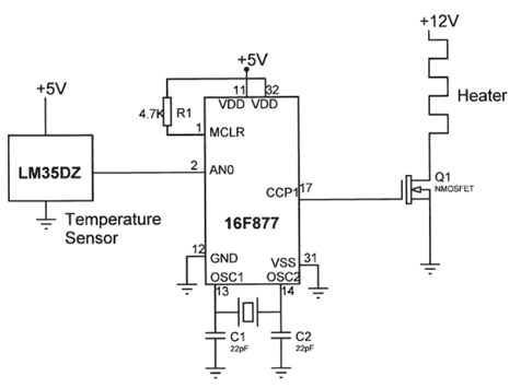
The electrical circuit diagram of this temperature control circuit consists of a 3-pin analog temperature sensor (LM35DZ), a built-in A/D converter microcontroller (PIC16F877), and the heater driver (IRL1004). The temperature control circuit utilizes the LM35DZ, a precision analog temperature sensor...
In a class project, each student was required to select one of three technology platforms to design, simulate, prototype, and build, including PCB layout and ordering, all within a ten-week timeframe. The available platforms were: H-bridge Motor Controller, Infrared...

The circuit involves a smart temperature control system utilizing DS1620 temperature sensors with a three-wire serial interface for managing a small electric heater. When the CD4044 type RS flip-flop is set to 1, the output Q becomes high, which...
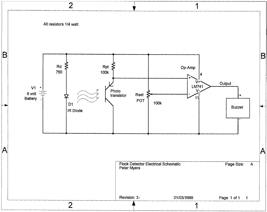
Construct a device to measure the depth of the flocculent layer in a lake. The flocculent layer is a mud layer with a consistency similar to water, making it challenging to measure its depth from the surface accurately. A...
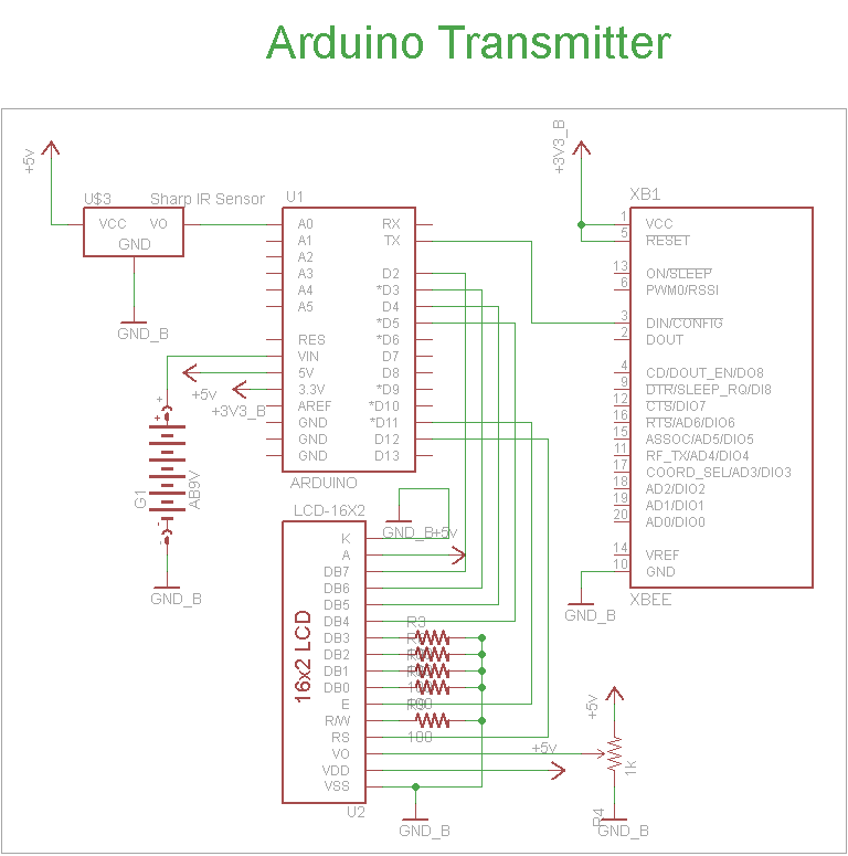
The schematic for the transmitter in this project consists of four main components: the Arduino UNO, the Sharp IR distance sensor, the XBee wireless modules, and a 16x2 LCD. The connections between these components are illustrated in the schematic....