
"Hee-Haw" Electronic Siren
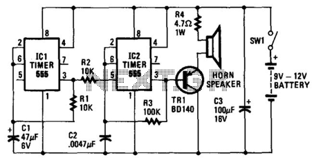
The circuit features an oscillator configuration utilizing integrated circuits (ICs) to generate sound signals. IC2 serves as the primary sound-producing element, where its output is directed to TR1, a transistor functioning as an amplifier. This amplification is crucial for driving a speaker, ensuring that the sound produced is audible. Resistor R4 is strategically placed in series with TR1 to safeguard the transistor by limiting the current flowing through it, thus preventing potential damage due to excessive current.
The frequency of oscillation produced by IC2 is a function of both the resistive and capacitive components in the circuit, specifically R3 and C2. These components form a timing network that dictates the oscillation rate. Moreover, the voltage applied to pin 5 of IC2 plays a significant role in modulating the frequency. By varying this voltage, the internal timing mechanism of IC2 is altered, resulting in different oscillation frequencies. This feature allows for dynamic sound modulation, which is essential for creating varied auditory signals.
In parallel, IC1 operates as a secondary oscillator, functioning at a much lower frequency of approximately 1 Hz. This slower oscillation is pivotal for generating control pulses that influence IC2. Each time IC1 completes a cycle, it triggers a high voltage at pin 3, which is directly connected to pin 5 of IC2. This interaction between the two ICs leads to a change in the output frequency of IC2, contributing to the distinctive "hee-haw" sound characteristic of the siren. The design demonstrates a well-coordinated interaction between multiple components to achieve a specific auditory output, emphasizing the importance of frequency modulation in sound synthesis applications. The oscillator based on IC2 is responsible for producing the sound. Its output is connected to the base of TRl, which amplifies it to drive the speaker. Resistor R4 is included in the circuit to limit the current through TRl to a safe and reasonable level. The oscillation frequency of IC2 is partially dependent on the values of R3 and C2. Another factor that governs the frequency of oscillation is the magnitude of voltage fed to pin 5 of IC2.
If a voltage of varying magnitude is fed to pin 5, the internal circuitry of the IC is forced to reset at a different rate, which changes the frequency. IC1 is also connected as an oscillator,but it runs much slower than IC2: around 1 Hz. Each time the IC triggers, the voltage at pin 3 goes high. As pin 3 is connected to pin 5 of IC2, this forces IC2 to change its note. That produces the "hee-haw" sound of the siren. 🔗 External reference
Related Circuits
Electronic Combination Lock. This circuit is very basic to build. To open the lock, which is connected to the K1 Load, you must press each momentary switch in the correct sequence. The electronic combination lock circuit provides a straightforward and...
The transformer OCL and capacitor C1 create a tank circuit, which is coupled with sufficient turns to drive the grid in the lower left-hand winding. The output circuit is connected through a separate winding. For optimal waveform characteristics in...
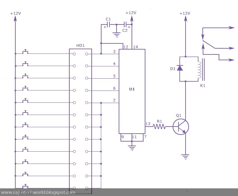
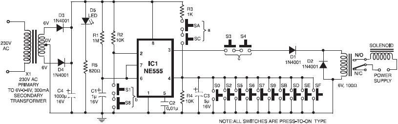
This circuit diagram represents a simple electronic combination lock using the CI LS7220 integrated circuit (IC). The circuit is designed to activate a relay for controlling a device based on a preset combination of four digits. It operates within...
This circuit diagram illustrates a simple electronic combination lock utilizing the IC LS7220. The circuit is designed to activate a relay for controlling any device (turning it on and off) when a specific combination of four digits is entered....
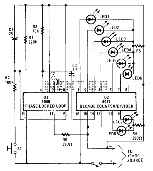
The circuit utilizes a 4046 Phase-Locked Loop (PLL) that incorporates a voltage-controlled oscillator (VCO), two phase comparators, a source follower, and a Zener diode to generate a low-frequency pulsed output of approximately 40 Hz. The frequency range of the...
A simple electronic key code lock circuit that requires few external components can be constructed using this schematic diagram. This electronic key code lock circuit is based on a common 555 timer circuit and other standard components. This low-cost...