
Electronic Combination Lock
The electronic combination lock circuit provides a straightforward and effective method for securing access through a simple keypad interface. The circuit typically comprises a series of momentary push-button switches, each representing a digit in a predetermined code. When the correct sequence of buttons is pressed, the circuit activates a relay or a transistor switch, which in turn controls the K1 Load, allowing for the locking mechanism to be disengaged.
The design often includes a microcontroller that manages the input from the switches, comparing the pressed sequence against the stored combination. The microcontroller can be programmed to allow for a limited number of incorrect attempts, enhancing security by temporarily disabling the lock after a certain threshold is reached.
For implementation, the circuit requires a power supply, a microcontroller (such as an Arduino or PIC), and a relay module to handle the load. Each switch is connected to a digital input pin on the microcontroller, and pull-down resistors may be used to ensure stable readings when the buttons are not pressed.
In addition, visual or audible feedback can be integrated into the design, such as LEDs or buzzers, to indicate correct or incorrect inputs, further improving user interaction. The layout should be designed to minimize noise and interference, ensuring reliable operation in various environments.
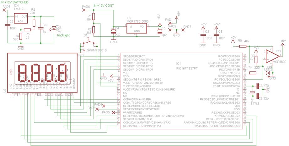
Overall, this electronic combination lock circuit is an excellent project for beginners in electronics, providing hands-on experience with microcontrollers, input devices, and relay control systems.Electronic Combination Lock. This circuit is very basic to build. To open a the lock which is connected to the K1 Load you must press each momentary switch in the correct sequence. The. 🔗 External reference
Related Circuits
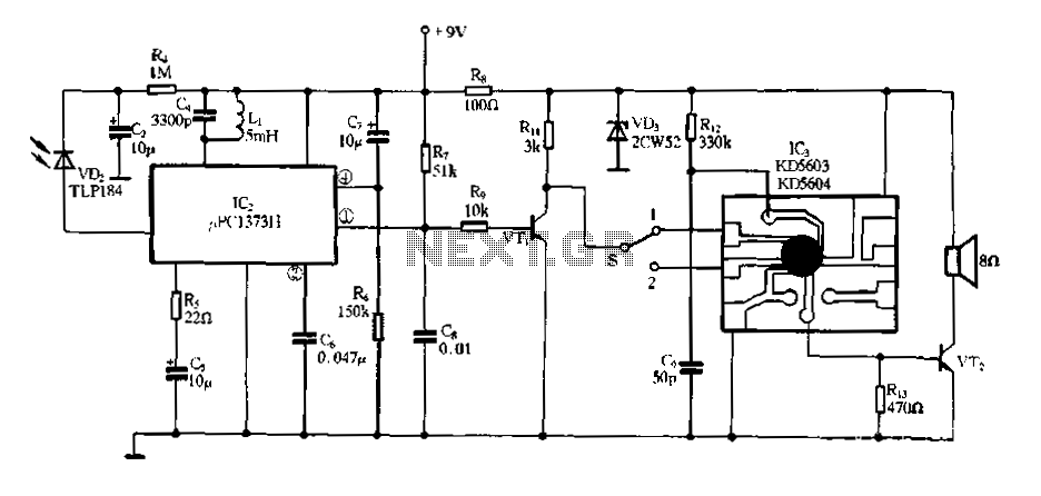
Electronic Miss Manners infrared receiver and voice circuits The Electronic Miss Manners system integrates an infrared (IR) receiver with voice circuits to facilitate communication and interaction. The IR receiver is designed to detect signals emitted from a remote control or...
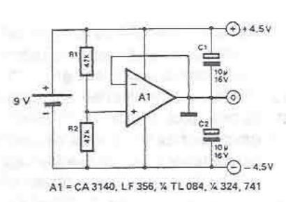
A symmetrical power supply can be designed using this circuit diagram. This symmetrical power supply is constructed with a simple operational amplifier and some classic electronic components. Resistors R1 and R2 form a high impedance voltage divider. The operational...
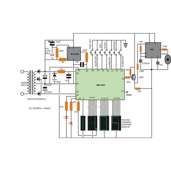
Creating a high-end, precise digital LED clock is now as straightforward as preparing noodles. This article outlines the process of constructing a digital clock using readily available electronic chips, such as the National Semiconductor MM5402 clock IC, along with...
This device is designed to replace the original digital clock in a Fiat Ducato manufactured between 1992 and 1994. It is mounted above the inside rearview mirror. The original clock has limitations, including poor accuracy, a singular time display,...
This electronic organ circuit is straightforward to construct and primarily consists of an emitter-coupled oscillator formed by transistors T2 and T3. A square wave voltage can be obtained from the collector of T3 (X2), which imparts a clarinet-like quality...

The electronic schematic of the Light Detector Robot can be divided into three main components: the sensor, the microcontroller, and the DC motor driver. The light sensor utilized in this design is a Light Dependent Resistor (LDR), which alters...