
HF 1-30MHz linear amplifier

The circuit design utilizes the BC547 transistors in a push-pull configuration to achieve linear amplification of RF signals across the HF band. The amplifier is capable of delivering an output power of 500mW, making it suitable for various applications in amateur radio and RF experimentation. The absence of RF neutralization simplifies the design, allowing for a compact layout on a copper-clad board measuring 45mm by 17mm.
The construction involves a battery supply rail formed by a 44mm long copper strip, which is adhered to the board with superglue. Decoupling capacitors of 10nF and 33nF are strategically placed at both ends of the board to ensure stable operation and minimize noise. The transformer T1 is critical in matching the drive impedance, with a primary winding of 14 turns of 0.1mm diameter wire and a secondary winding configured as 1+1 turns of 0.2mm wire, utilizing small ferrite beads for efficient magnetic coupling.
A second transformer, T2, is constructed using two ferrite rings and features an 11-turn trifilar winding technique, enhancing the coupling and efficiency of the output stage. The transistors are mounted vertically to facilitate heat dissipation and ensure robust performance. This design choice, along with the careful winding of the transformers, contributes to the amplifier's exceptional spectral purity, evidenced by the lack of unwanted harmonics or spurious signals during testing.
The amplifier achieves a gain of 30dB, enabling effective signal amplification when driven by standard signal generators. However, caution is advised when selecting the driving source, as certain generators like the Marconi TF995 may introduce unwanted noise. The operational bandwidth of the amplifier extends into the VHF range, although the gain diminishes at higher frequencies, stabilizing around unity at 100MHz. The performance characteristics are validated through spectrum analysis, demonstrating the amplifier's capability to deliver clean, amplified signals across the specified frequency range.This project was a particular surprise for me in that the BC547 (equiv 2N2222) can be used to build a 500mW linear amplifer covering the entire HF band with excelent spectral purity and no neutralising at all. Ugly-bug construction was used but I dare say that the good results are partly to do with the method of construction.
The circuit is fairly straight-forward and does not even need any form of RF neutralising. Two pairs of BC547 transistors are used in a push-pull type of output stage, biassed by a single diode and resistor. The driver is also very conventional using T1 to transform the drive impedance to a very low value for the output pairs.
The amplifier is constructed on a piece of copper-clad board 45mm long by 17mm wide. Superglue a 44mm long by 3mm wide strip of copper-clad board along the center. This will become the battery supply rail. Using a sharp knife, remove some copper to form a 3mm x 3mm pad at one end of the battery rail to form the RF output terminal. Next fit the 10n and 33n decoupling capacitors; one pair at either end. These should lay flat on the board. The rest is easy after you see the photographs. T1 primary is 14-turns of very thin wire (0.1mm Dia.) and the secondary is 1+1 turn of thin wire (0.2mm Dia.).
T1 former is two of the smallest ferrite beads I could find. You can just see it in the left-hand photograph above. T1 is composed of two grey ferrite beads. The right-hand photograph shows T2 and the mounting of the two output pairs of BC547 transistors. T2 is a little special. I found two small ferrite rings in the junk-box and decided to give them a try. The windings are 11-turns triflar wound using thin wire (0.2mm Dia.): Twist together three 1-metre lengths of thin enamelled wire. Wind 11-turns through the ferrite rings (1-turn is passed through both rings). Do NOT cut off the surplus yet. Identify A1-A2, B1-B2, C1-C2 using an ohm-meter. Thread each end of C1 and C2 back through the ferrite rings to add 2-1/2 extra turns to each end. Winding C should now have a total of 16-turns. Twist together A2 and B1 and connect to the positive battery rail. Connect A1 and B2 to the BC547 collectors. The five transistors are all mounted on their heads using super-glue and with their legs in the air spread wide apart (Hey!
this sounds kinda' pornographic!!). The finished linear amplifer does not look very pretty but it is very small. It is less than 10mm high and looks like this. Here you can see it beside my parker pen for comparison (I thought it would be better than a common 1-crown coin). Spectral purity was the biggest surprise; nothing to see on the analyser! Not a single unwanted blip, peak or spurious signal over -30dBm which is about 60dB down on the fundamental.
Not bad for "ugly-bug" construction. The amplifer has a 30dB gain so the full output can be achieved when driven from a normal signal generator. Note that Heterodyne generators, such as the Marconi TF995, usually have a very dirty output signal and are not suitable as a driver as the basis of a transmitter; just because it cost you money does not mean it is perfect (as any ham's neighbour owning an Onkyo colour TV will testify).
The bandwidth extends well into the VHF region but the gain is almost unity at 100MHz. Here is the spectrum analyser displays. The left-hand photograph shows a sweep of the band from 0-30MHz centered on 15MHz. The input is 17MHz. The right-hand photograph shows the frequency response, scale is also 3MHz/division and the top line is +30dBm (1-watt) on both traces. The scales are logarithmic with 10dB per division. 🔗 External reference
Related Circuits
The 30-watt amplifier schematic provided below offers a power boost from an input of 4 watts to 6 watts. This circuit is designed to operate within the 88-108 MHz FM broadcast band. It demonstrates stability and delivers a clean...
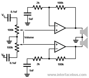
The 100k potentiometers adjust the voltage levels reaching the operational amplifiers (Op Amps). A dual ganged 100K-Ohm audio-taper potentiometer is preferred over a linear taper potentiometer. In some instances, this component may be referred to as a ganged stereo...

The signal can be converted by piezoelectric films in various ways, including thermal to electrical (temperature sensor) and mechanical to electrical (microphone). Piezoelectric films are materials that generate an electrical charge in response to applied mechanical stress or temperature changes....

This design concept addresses a major challenge associated with the use of photodiodes in high-speed applications such as barcode scanners, CD-ROMs, and DVDs, specifically the high output capacitance of the diode. The critical component in the circuit is the...
The video amplifier depicted in the diagram is a well-established design that is both simple and effective. However, there is a risk of damaging the transistors if the potentiometers (black level and signal amplitude) are set to their extreme...
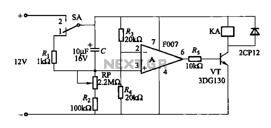
A delay circuit utilizing an operational amplifier functions as a comparator, providing high timing accuracy. The timer's delay range is from 1 to 30 seconds. The delay time is determined by resistors Ri, RP, and capacitor C. By adjusting...