
Improved Photodiode Pre-Amp Uses Current-Feedback Amplifier

The circuit leverages the AD8014 operational amplifier, known for its high-speed performance and low output capacitance, making it suitable for applications where rapid signal processing is essential. The AD8014 features a bandwidth of 100 MHz and a slew rate of 2000 V/µs, allowing it to effectively amplify the small signals generated by photodiodes in fast applications.
In typical configurations, the photodiode is connected in a reverse bias mode to enhance its response time. The output from the photodiode is fed directly into the non-inverting input of the AD8014, where it is amplified. To minimize noise and ensure stability, appropriate feedback resistors and capacitors are used in the circuit design. This configuration not only mitigates the effects of the diode's inherent capacitance but also optimizes the overall frequency response of the system.
The circuit may also include additional components such as biasing resistors, which help to set the operating point of the photodiode, and filtering capacitors to eliminate high-frequency noise. Proper layout techniques should be employed to reduce parasitic capacitance and inductance, which can adversely affect the circuit's performance.
Overall, this design effectively enhances the performance of photodiodes in high-speed applications by utilizing the AD8014, ensuring reliable and efficient operation in systems requiring rapid data processing.This design idea overcomes a significant problem with using photodiodes in fast applications like barcode scanners, CD-ROMs, and DVDs--high output capacitance of the diode. The key part in the circuit is the Analog Devices AD8014 🔗 External reference
Related Circuits
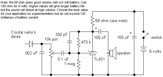
A simple audio amplifier application using a TL431 voltage regulator. The amplifier is designed to produce room-filling sound from a standard clear radio equipped with a long-wire antenna and suitable ground. The chip is similar in complexity to a...
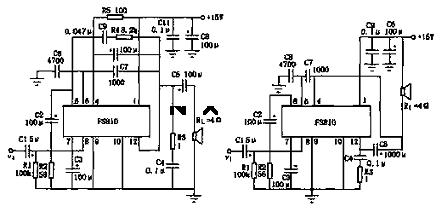
The FS810 circuit serves as a practical implementation of an integrated power amplifier. The FS810 is designed for high-performance use in high-end tape recorders and audio equipment. In the schematic, the speaker is connected to the output capacitor C5...
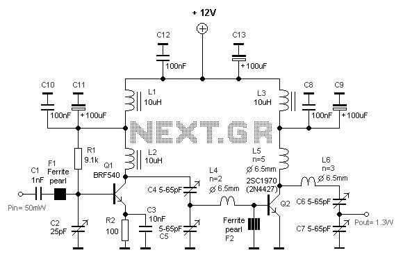
This diagram represents a schematic of an RF amplifier circuit. The circuit is designed to amplify an RF signal from approximately 100 mW input power to 1.3 W output power. It utilizes a general NPN RF transistor, specifically the...
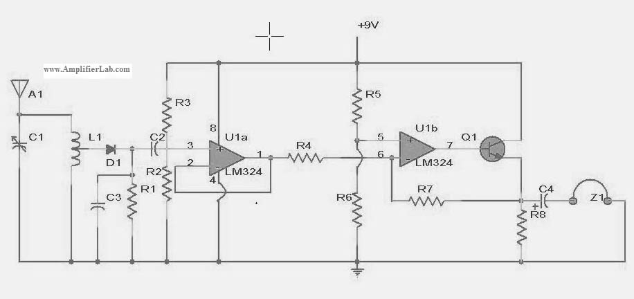
The following circuit illustrates a power amplifier electronic circuit, specifically a tube audio RF amplifier circuit diagram. This circuit is based on the LM324 integrated circuit. The power amplifier circuit utilizing the LM324 operational amplifier is designed to enhance audio...
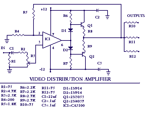
With the amount of equipment in home entertainment centers today the need to be able to vary the gain of the audio or video signal is needed. I found this particular circuit helpful when used in conjunction with the...
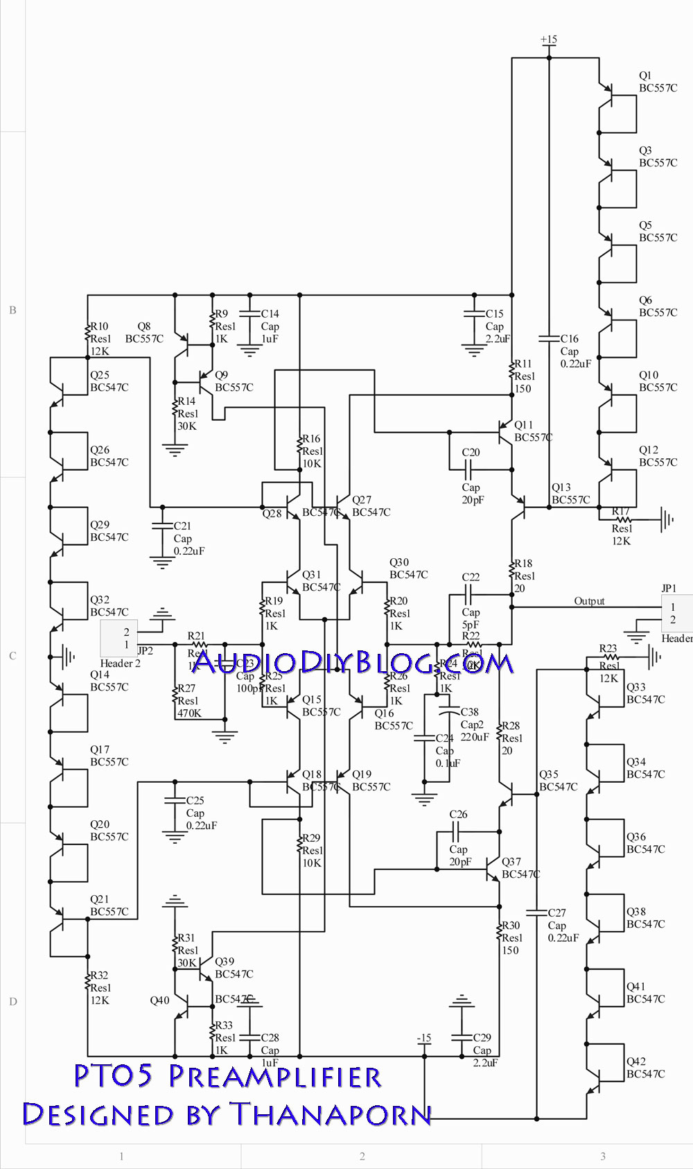
The next stage operates in conjunction with the first stage and is fully complementary. A cascode circuit is included to enhance the linearity of the amplifiers. This cascode circuit requires a constant reference voltage for biasing to activate the...