
High-Accuracy Thermometer

The circuit design employs a platinum Resistance Temperature Detector (RTD) configured in a Wheatstone bridge arrangement, which is essential for precise temperature measurement. The current source drives the RTD, allowing for a consistent current flow that generates a voltage proportional to the resistance change of the RTD due to temperature variations. The LT1009 operational amplifier is utilized for its high precision and stability, ensuring minimal drift and noise in the measurements.
The bridge output is sensitive to temperature changes, and the differential amplifier configuration of A3 enhances the signal while simultaneously correcting for any nonlinearity introduced by the RTD. The feedback mechanism through the resistive divider allows for fine-tuning of the output, ensuring that the temperature readings remain accurate across the specified range. This feedback loop is vital for maintaining the integrity of the measurement, especially in applications where precision is critical.
In terms of calibration, it is essential to follow a systematic approach as outlined in the accompanying diagram to ensure that the thermometer operates within its specified accuracy limits. Calibration typically involves comparing the thermometer readings against a known temperature standard and adjusting the feedback network to account for any discrepancies.
Overall, this circuit exemplifies a sophisticated approach to temperature measurement, integrating advanced components and techniques to achieve high accuracy and reliability in various applications, including industrial and laboratory environments. This circuit combines a current source and a platinum RTD bridge to form a complete high-accuracy thermometer. Th e ground-referred RTD sits in a bridge that is composed of the current drive and the LT1009 biased resistor string. The current drive allows the voltage across the RTD to vary directly with its temperature-induced resistance shift.
The difference between this potential and that of the opposing bridge leg forms the bridge output. The RTD"s constant drive forces the voltage across it to vary with its resistance, which has a nearly linear positive temperature coefficient. The nonlinearity could cause several degrees of error over the circuit"s 0°C -400°C operating range.
The bridge"s output is fed to instrumentation amplifier A3, which provides differential gain, while simultaneously supplying nonlinearity correction. The correction is implemented by feeding a portion of A3"s output back to Al"s input via the 10- to 250-KOhmhm divider.
This causes the current supplied to RP to slightly shift with its operating point, compensating sensor nonlinearity to within ±0.05°C. A1B, providing additional scaled gain, furnishes the circuit output. To calibrate this circuit, follow the procedure given in the diagram.
Related Circuits
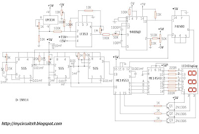
This circuit consists of a temperature sensor, amplifier, voltage-to-frequency (V/F) converter, a three-digit binary coded decimal (BCD) counter, a time base, and seven-segment LED displays. In addition to the 9400 V/F converter, other integrated circuits (ICs) required for this...
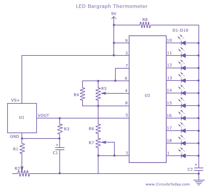
An LED thermometer that can function as a temperature sensor or temperature measurement circuit, utilizing the LM34 for Fahrenheit display or the LM35 for degree Celsius display. The LED thermometer circuit is designed to provide accurate temperature readings using either...

This digital thermometer circuit diagram utilizes a common 1N4148 diode as the temperature sensor. The diode's temperature coefficient of -2 mV/°C is leveraged to create an accurate electronic thermometer. A digital multimeter is employed to display the measured temperature,...
The receiver circuit and display module will receive the high-frequency AC power cord and decode it to provide actual temperature readings using digital IC No. CD4553 (Three-digit BCD Counter IC) and IC CD4511 (BCD-to-7-Segment Latch/Decoder/Driver IC). The frequency pulses...
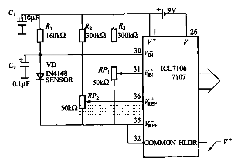
A diode temperature sensor is utilized in a 3-digit thermometer, featuring a 3-digit A/D converter and display driver IC L7106/7107. This configuration amplifies the signal, performs A/D conversion, and executes a series of decoding and display driver processes to...
A new generation of intelligent, scriptable sensors/controllers is on the horizon. Traditionally, many simple machines utilized separate thermometer and control units. In contrast, this design presents a unified thermometric controller that can be programmed with simple scripts. It incorporates...