
High Current 13.8V Power Supply

The described power supply circuit is a straightforward design intended for applications requiring a significant current output. It is capable of delivering up to 20 Amps intermittently and 10 Amps continuously, making it suitable for various electronic projects and testing scenarios. The circuit's flexibility allows for scalability; by upgrading components such as the transformer, bridge rectifier, capacitors, and output transistors, the current capacity can be increased substantially.
To achieve higher current ratings, a larger transformer should be selected to provide adequate voltage and current levels. The bridge rectifier must also be rated to handle the increased current, ensuring that it can effectively convert the AC voltage from the transformer to a stable DC output without overheating or failing. The use of additional capacitors is crucial for smoothing the output voltage and reducing ripple, which is especially important in high-current applications where load variations can lead to significant fluctuations in voltage.
The inclusion of output transistors plays a vital role in the circuit's ability to handle high currents. By choosing transistors with a higher current rating and appropriate thermal management, the circuit can be pushed to deliver even more power. For instance, the use of a 5A TO3 regulator IC can support currents up to 100A, depending on the thermal design and the overall circuit configuration. It is important to ensure that sufficient heat sinking and cooling mechanisms are employed to maintain the reliability of the circuit at higher currents.
This power supply design serves as a robust foundation that can be tailored to meet specific requirements, whether for hobbyist projects or more demanding industrial applications. With careful consideration of the component ratings and thermal management, it is possible to achieve outputs of up to 500A, should the application necessitate such high current levels.As is commonly the case, this supply was born of necessity. There is absolutely nothing special about the circuit, except that as shown, it is quite capable of up to 20 Amps intermittently or 10A continuous. Simply use a bigger transformer, bridge rectifier and more capacitors and output transistors to get more current.
The basic circuit should be good for up to 100A or so, using a 5A TO3 regulator IC, but it can obviously be increased further (if you really do need a 500A supply!). 🔗 External reference
Related Circuits
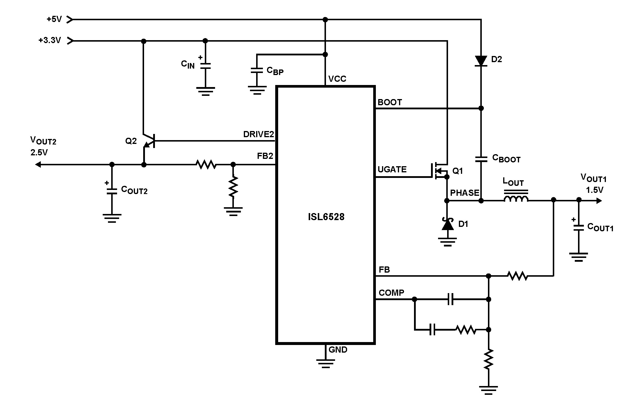
The ISL6528 offers power control and protection for two output voltages in high-performance graphics cards and other embedded processor applications. This dual-output controller drives an N-Channel MOSFET in a standard buck topology and an NPN pass transistor in a...
Readers who do not wish to modify the power supply of an old PC into a suitable halogen power source may find the current design a welcome alternative. The circuit does not require any alterations to the power supply....
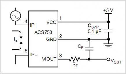
The AD537 is a monolithic voltage-to-frequency (V-F) converter that includes an input amplifier, a precision oscillator system, an accurate internal reference generator, and a high-current output stage. A single external resistor-capacitor (RC) network is sufficient to configure any full-scale...
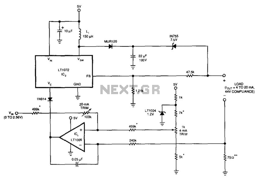
This 5-V circuit employs a servo-controlled DC/DC converter to generate the compliance voltage necessary for current requirements. It is designed to drive 4 to 20 mA into loads as high as 2200 ohms with 44 V of compliance. The...

If the total circuit resistance can be significantly reduced to less than 0.1 Ohm and a load of 0.4 Ohm or less is connected, over 1 kilowatt of free electrical energy can be obtained. There are two discrete voltage...

R1 controls the trip-point of the circuit. adjust it accordingly. to reverse the logic (have the led light up when the battery has at least X amount of power,) connect the led to ground through R4. More: all resistors...