
High Current Low-Dropout Voltage Regulator

The circuit functions as a power supply system that converts the output from a solar panel into a usable voltage level for a laptop. The solar panel generates a variable voltage depending on sunlight conditions, which can typically range from 18V to 24V under optimal conditions. To ensure that the laptop receives a stable voltage of 12V, a linear voltage regulator is employed in the circuit.
The linear regulator operates by dissipating excess voltage as heat, allowing the output voltage to remain constant at the required 12V. The input current to the regulator must be sufficient to meet the laptop's power requirement, which is 3.3A. Therefore, the input to the regulator must be higher than the output voltage, and the power dissipation in the regulator must be considered to prevent overheating.
To enhance efficiency and reliability, additional components such as capacitors may be included in the circuit. Input and output capacitors help stabilize the voltage and filter any noise from the solar panel. A heat sink may also be necessary for the linear regulator to manage the heat generated during operation, especially when the input voltage is significantly higher than the output voltage.
Furthermore, a protection circuit can be integrated to prevent damage to the laptop from overvoltage or reverse polarity. This may involve the use of diodes and fuses to safeguard the system. The overall design must ensure that the solar power setup can adequately supply the necessary current while maintaining the required voltage levels to power the laptop efficiently.This circuit was designed to allow a laptop computer to be powered from a solar power setup. The computer requires 12V at 3.3A. The circuit is a linear re.. 🔗 External reference
Related Circuits
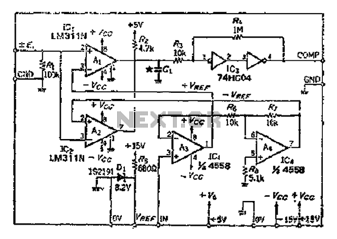
An AI comparator input is connected to a reference resistor (Rl). When the output reaches a specified level, known as VREP (absolute value), the output also stabilizes at this level. The outputs Ai and As are connected to an...
This high voltage converter circuit begins with a 30-volt power supply and is capable of delivering output voltages ranging from 0 to 3 kV for version 1, or from 0 to 10 kV for version 2. The high voltage converter...
This project is a high precision digital thermometer which indicates the temperature on the seven segment display. It has a resolution of 0.06 °C. The 1-wire temperature sensor IC from Maxim semiconductors is used as the sensor. The DS18S20...
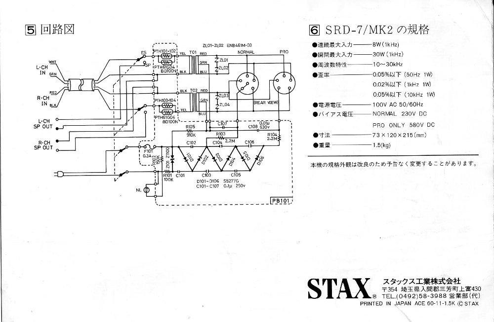
This project enables the construction of a high-quality version of the Stax SRD-7MkII headphone adapter, allowing the use of an existing amplifier to drive Stax headphones. To determine compatibility with specific amplifiers, users are encouraged to consult with Birgir....
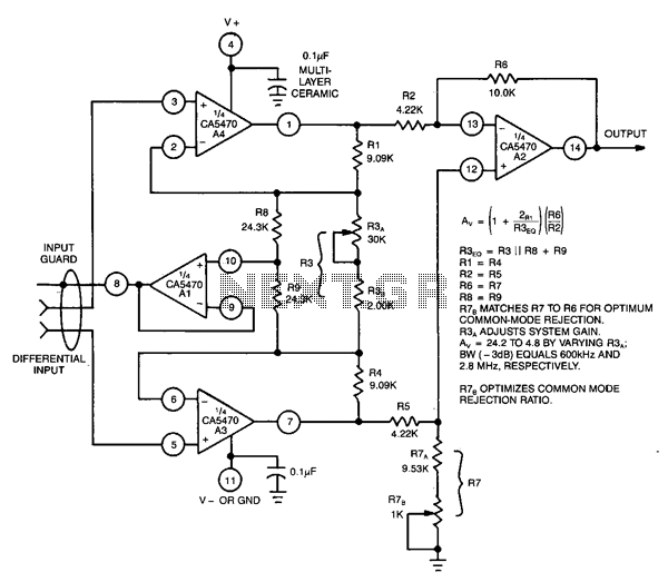
This circuit utilizes a CA5470 quad microprocessor BiMOS-E operational amplifier. Amplifiers A1 and A2 are configured as a cross-coupled differential input and differential output preamplifier stage, while A3 is responsible for input guard-banding. Additionally, amplifier A4 converts the differential...
A circuit for monitoring supply voltages of ±5 V and ±12 V can be constructed as shown in the diagram. It is significantly simpler than the typical monitors that utilize comparators and AND gates. The circuit is not designed...