
High impedance DC Voltmeter by IC CA313048
The described circuit employs the CA3140 operational amplifier, which features a MOSFET input stage, providing high input impedance essential for accurate voltage measurements in a DC voltmeter application. The switch S1 serves as a range selector, enabling the user to select between different measurement ranges, effectively altering the gain of the circuit to accommodate voltages up to 100V.
The voltage divider, consisting of precision resistors, is designed to limit the input impedance to 10MΩ. This impedance ensures minimal loading on the circuit being measured, preserving the integrity of the voltage reading. The mechanical zero adjustment allows for initial calibration of the meter, ensuring the pointer aligns correctly with the zero mark before any measurements are taken.
During the calibration process, TR1 is adjusted while the input is shorted, allowing the user to achieve a precise zero indication on the display. This step is crucial for ensuring that any subsequent voltage measurements are accurate and reliable. TR2 is then utilized to calibrate the meter across the selected ranges. The full-scale deflection settings of 1V, 10V, and 100V are established through careful adjustment of TR2, ensuring that the voltmeter can accurately represent the voltage levels within the specified ranges.
The supply voltage requirements for this circuit range from 8V to 20V, providing flexibility in power supply options while maintaining a low current consumption of less than 6mA at 12V, which is advantageous for battery-operated applications. The overall accuracy of the voltmeter is contingent upon the precision of the 100mA instrument utilized, as well as the diligence exercised during the calibration process, highlighting the importance of using high-quality components and meticulous adjustment techniques in achieving reliable voltage measurements.The MOSFET input of the CA3140 makes it ideally suited for use in a high impedance DC voltmeter. Switch S1 is the range selector. The input impedance is limited to 10M by the resistors used in the voltage divider, but this is still a very acceptable value. Before switching on for the first time, the mechanical zero adjustment of the 100m A instrum ent should be set so that the pointer rests just below zero on the scale. The unit is then switched on and with the input shorted, TR1 is adjusted until an exact zero indication is obtained. The TR2 is used for calibrating the meter so that the full scale deflection in the three ranges is 1V, 10V and 100V.
The supply voltage can be anything between 8 and 20V. The current consumption is less than 6mA at 12V. The accuracy of this voltmeter depends mainly on the quality of the 100m A instrument and the care with which the unit has been calibrated. 🔗 External reference
Related Circuits
The copyright of this circuit is owned by Smart Kit Electronics. This document discusses improvements and modifications based on the original schematic. It describes a straightforward yet highly accurate and useful digital voltmeter designed as a panel meter, suitable...
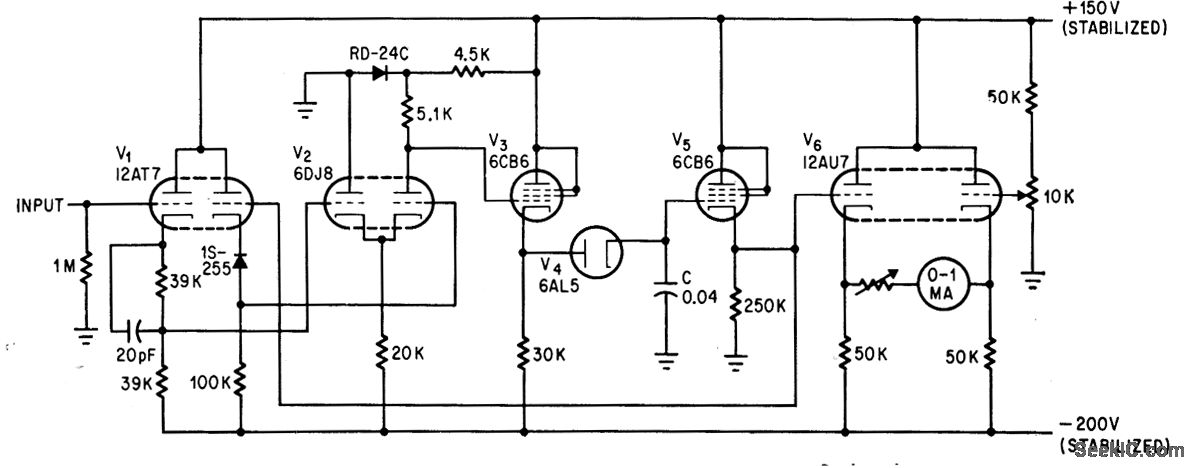
The addition of a dual-triode amplifier (V2) to a conventional peak voltmeter reduces the charging time constant while increasing the available time for measuring peak values. Linearity is maintained up to 40 volts. The integration of a dual-triode amplifier into...
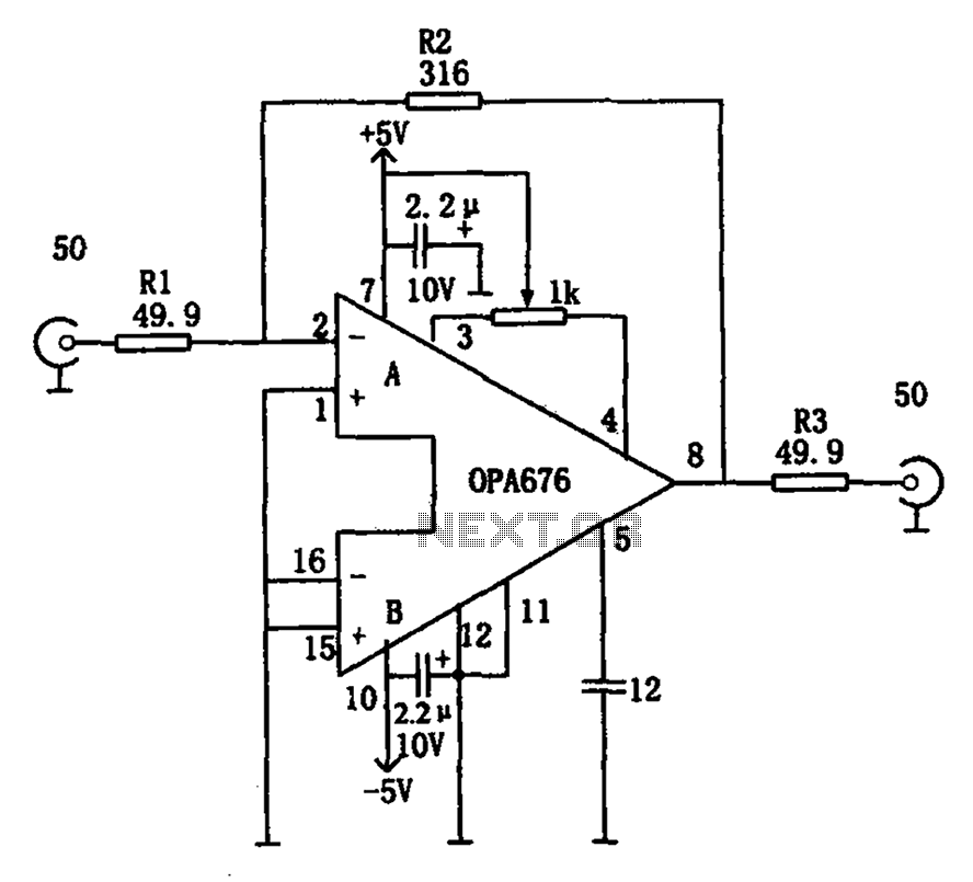
The circuit features a broadband video amplifier with a 50-ohm input/output impedance. To ensure optimal signal transmission and minimize reflected signals, it is often necessary to match the input and output impedances of the amplifier. The broadband video amplifier...
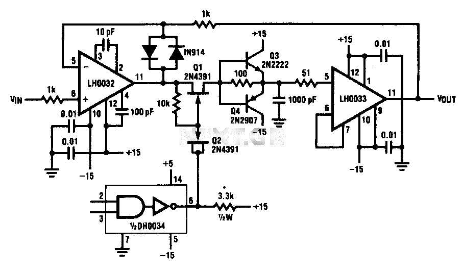
This circuit demonstrates a 10 V acquisition time of 900 ns with 0% accuracy and a droop rate of only 100 µV/ms at an ambient temperature of 25°C. A faster acquisition time can be achieved by using a smaller...
This high voltage converter circuit operates from a 30-volt power supply and can output a voltage ranging from 0 to 3 kV in version 1 or from 0 to 10 kV in version 2. The high voltage converter circuit is...
The LV2282VA is an FM Transmitter integrated circuit (IC). The multiplex (MPX) block generates a stereo modulated composite signal from left (L) and right (R) audio inputs. The radio frequency voltage-controlled oscillator (RF VCO) incorporates an FM modulation function....
Warning: include(partials/cookie-banner.php): Failed to open stream: Permission denied in /var/www/html/nextgr/view-circuit.php on line 713
Warning: include(): Failed opening 'partials/cookie-banner.php' for inclusion (include_path='.:/usr/share/php') in /var/www/html/nextgr/view-circuit.php on line 713