
PEAK VOLTMETER FOR NARROW PULSES

The integration of a dual-triode amplifier into a peak voltmeter circuit significantly enhances its performance by optimizing the measurement of transient signals. The dual-triode configuration allows for improved signal amplification, which is crucial for accurately capturing peak voltages in rapidly changing electrical signals.
In this setup, the dual-triode amplifier (V2) serves to minimize the charging time constant of the voltmeter. This reduction is critical because it allows the voltmeter to respond more quickly to changes in voltage, thereby providing a more accurate representation of peak values. The amplifier's design contributes to a high input impedance, which prevents loading effects that could distort the measurement.
The circuit operates effectively within a voltage range of up to 40 volts, maintaining good linearity throughout this range. This characteristic is essential for applications where precise voltage measurements are required, such as in audio electronics or signal processing. The dual-triode configuration ensures that the amplifier can handle variations in input signals without significant distortion, thus preserving the integrity of the measured peak values.
Overall, the enhancement of the peak voltmeter's response through the addition of a dual-triode amplifier exemplifies a practical application of amplifier technology in improving measurement accuracy and speed in electronic instrumentation.Addition of dual-triode amplifier V2 to conventional peak voltmeter reduces charging time constant while increasing available time for measuring peak value. Linearity is good up to 40 v. -M. Uno, Amplifier Improves Peak Voltmeter Response, Electronics, 37:14, p 73. 🔗 External reference
Related Circuits
The circuit-delay relay for speakers serves as a delay mechanism that prevents the immediate activation of speakers when the amplifier is powered on. This feature is designed to protect the speakers from potential damage caused by sudden power surges....
In a stereo system, it is often important to determine whether the speakers are polarized. This can be especially problematic if the speaker cables lack polarity markings. The circuit described will assist in identifying the correct terminals for the...
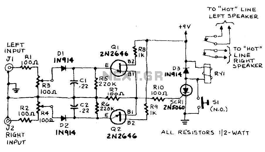
The circuit input is derived from the terminal loudspeaker or amplifier output jacks. If the right channel signal is sufficiently strong to charge capacitor C1 to a potential that exceeds the breakdown voltage of the emitter of transistor Q1,...

Power Amplifier Speaker Protection Circuit Schematic. When a power amplifier is switched on, a loud thump sound is often heard due to a sudden heavy discharge. The power amplifier speaker protection circuit is designed to prevent loud thump sounds during...
Listen and share music wherever you go with the mini speaker system project. This project allows for music playback in various locations such as dorms, cubicles, or the beach. It serves as an excellent introduction to circuit systems, featuring...
A basic digital voltmeter circuit utilizing the Harris Semiconductor ICL7107 is presented. It operates within a 2-V range. Calibration involves applying a known voltage of 1.2 V to the input and adjusting resistor R3 to achieve an accurate reading...