
Computer fan speed tacho out circuit

The circuit described is a common configuration found in 3-wire computer fans, which typically consist of three connections: power (VCC), ground (GND), and a tachometer output (TACH). The power and ground wires supply the necessary voltage to operate the fan motor, while the tachometer output provides feedback regarding the fan's rotational speed.
To access the tachometer circuit, it is necessary to peel off a sticker from the fan hub, revealing a pin connected to one of the motor windings. This pin is crucial for measuring the speed of the fan. The fan's internal circuitry generates a pulse signal on the TACH line, which corresponds to the rotation of the fan blades; typically, one pulse is produced for each revolution.
The TACH signal is typically a square wave, where the frequency of the pulses is directly proportional to the fan speed. This signal can be interfaced with a microcontroller or a motherboard fan controller, allowing the system to monitor and adjust the fan speed as needed for thermal management.
In terms of schematic representation, the fan circuit would include a DC motor connected to the power supply, with the TACH output line connected to a microcontroller input pin. Additional components may include a resistor for signal conditioning and capacitors for noise filtering, ensuring a clean and stable output signal for accurate speed monitoring. The design allows for efficient operation and effective thermal control in computer systems, enhancing overall performance and reliability.You will find this identical circuit inside most 3 wire computer fans with speed monitoring output to the motherboard. Peel off the sticker from the fan hub in order to access a motor winding pin for connecting up the tacho circuit.
🔗 External reference
Related Circuits
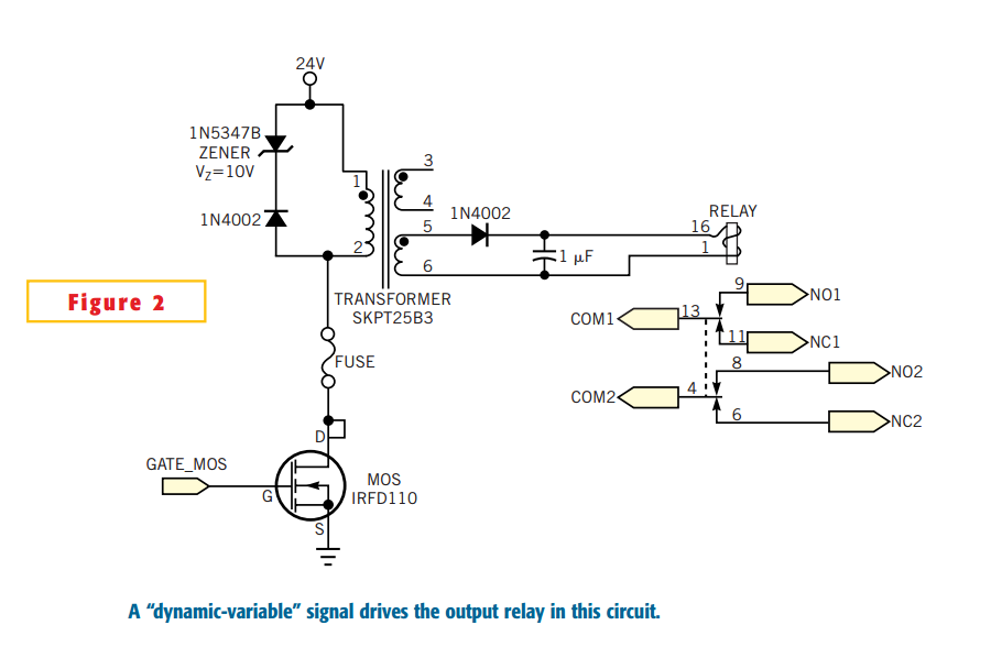
Many electronic-control systems have digital outputs that use transistors. One method of improving the security in these outputs is to use an oscillating signal to represent a logic-high state instead of a fixed voltage level. This type of signal,...

This page contains various small circuits created over time. Some circuits are trivial, while others are more complex, but all are intended to be useful for a variety of projects. Most include both the schematics and the source (KiCad)...

With this circuit we can create a altered sound of siren. The oscillator IC1a-b is constituted by two gates NAND, oscillating in very low frequency. This oscillation drive the IC2, that is a electronic switch, which opens and closes...

This is a small circuit designed as an insect repellent, targeting mosquitoes and birds by producing high-frequency audio signals. These signals interfere with the hearing of insects, making it unbearable for them, causing them to flee. The operation of...

The VE1 preamplifier utilizes a low muscle, low resistance double triode 6N6 configuration, with separate halves for the left and right audio channels. The design operates within the CPI framework. It promotes the use of high-level VE2 household low...

The call is triggered by the position sensing circuit, which activates the control circuit and SOS alarm circuit. This system is designed for critically ill patients or to assist disabled individuals in the event of a fall. A position...