
Voltage Controlled PWM Generator

The PWM circuit operates by utilizing a triangular waveform generator and a comparator. The triangular waveform is generated through a simple oscillator circuit, which can be implemented using an operational amplifier configured in an astable multivibrator mode. The frequency of oscillation can be adjusted by changing the values of the resistors and capacitors in the circuit, allowing flexibility in the PWM frequency.
The comparator, which can also be an operational amplifier, compares the triangular waveform with the DC input voltage. When the DC voltage exceeds the triangular waveform, the output of the comparator toggles, generating a PWM signal. The duty cycle of the PWM signal is directly influenced by the DC input voltage; higher DC levels result in a higher duty cycle, while lower levels yield a lower duty cycle.
The use of a potentiometer as a voltage divider allows for easy adjustment of the DC input voltage, providing a practical means to control the duty cycle. The inclusion of a resistor in series with the potentiometer ensures stable operation by limiting the voltage drop across the circuit components.
For practical applications, the circuit can be powered from a variety of DC sources, and its versatility makes it suitable for controlling motors, LEDs, and other devices requiring variable power. The circuit's performance can be verified using an oscilloscope, which provides a visual representation of the PWM signal and its relationship with the triangular waveform and DC input voltage. The design is straightforward, making it accessible for experimentation and further development in PWM applications.Circuits that generates PWM pulses. Most of them will translate a resistor value into duty cycle change. Although that is handy and easy, sometimes a voltage controlled PWM generator is needed. There are of course those micro-controllers that could make almost any kind of PWM signal translation, but i preferred to study and create a circuit without the use of such chips. I tried to keep it as easy as can be, but without this reflecting to the accuracy and integrity of the output pulses. The operation is similar to the digital signal transmission using PWM signals. The DC input level voltage is compared to the current voltage of the triangular waveform. Every time those two levels have the same value, the output will change state. If the triangular waveform was on the rising edge, the output will go HIGH, otherwise the output will go LOW. The green waveforms are the triangular signals. The brown line is the DC voltage level. Finally, the red pulses are the output PWM. You can see how these pulses changes the duty cycle as the DC input level changes. You can find complete theory, details and drawing for the triangle wave oscillator in our relevant circuit.
I have used the first circuit and i added the same transistor with a slightly changed resistors. My goal was to amplify the circuit but shift it a little bit, to help the circuit achieve duty cycles from 0 to 100%. You could as well use another circuit for generating a triangular waveform. The oscillation frequency in our circuit is around 1. 5 KHz at the time, but this is not a critical value. You should keep in mind thought that the frequency of this triangle waveform will determine the PWM frequency.
To test the circuit, i needed a DC reference level. I used a simple 5K potentiometer implementing a voltage divider and i added a 1. 5K resistor as shown in the schematic. This resistor will prevent the DC voltage to fall too much under the bottom edge of the shifted triangle waveform. Therefore, the whole range of the potentiometer will have active influence on the PWM duty cycle. That is the most important characteristic of this circuit. You an use any kind of DC voltage level as input, as long as it remains equal or less than the power supply of this circuit.
The circuit is tested from 3. 3 to 12 volts, but i am sure that it an operate in much higher voltages. Actually, the transistor and the selected OP-AMP will put the final frontiers. I`m always impressed from applied theory! I love to see the results. Following, i have include some photos of the oscilloscope monitor, while i am changing the DC level. Three waveforms are shown. The green is the triangular waveform and the blue is the DC voltage level. I have put them one over the other with common ground. The bottom yellow waveform is the result of the voltage comparison from the two above lines. 🔗 External reference
Related Circuits
Pure sine wave inverters are optimal; however, they are costly to purchase or construct. Modified sine wave inverters can power certain equipment, while square wave inverters have more limitations. Pure sine wave inverters are highly regarded for their ability to...
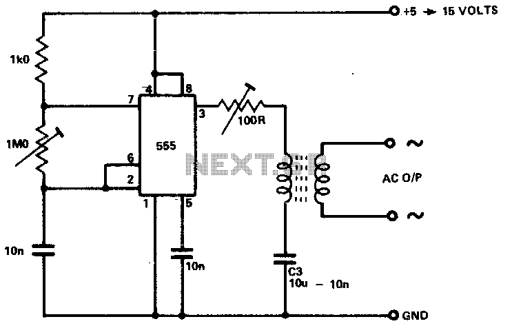
The circuit is designed to supply power for portable Geiger counters, dosimeter chargers, high resistance meters, and similar devices. The 555 timer integrated circuit (IC) operates in its multivibrator mode, with the frequency adjusted to optimize the characteristics of...
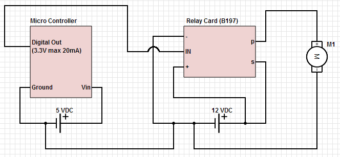
The objective is to control a 12 VDC device (on/off) from a microcontroller using a relay card. The relay requires a 12 VDC operating power supply. To achieve the control of a 12 VDC device using a microcontroller and a...
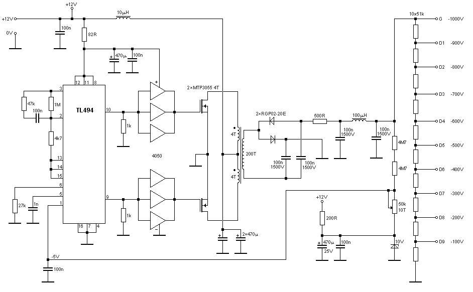
The schematic diagram originates from a circuit designed for a stable power supply ranging from -100V to -1000V. For further details, refer to the page that explains the circuit diagram associated with this power supply. This stable power supply...
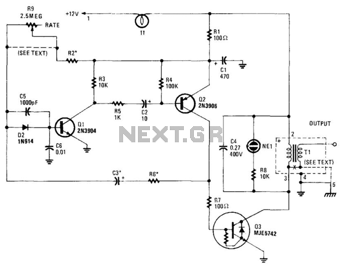
This high-voltage pulse supply generates pulses up to 30 kV. Q1 and Q2 form a multivibrator in conjunction with peripheral components R1 through R6, and C1, C2, C3, C5, C6, and D2. R9 adjusts the pulse repetition rate, while...
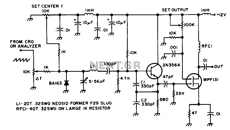
This circuit is utilized to observe the response of an intermediate frequency (IF) amplifier or a filter. It can be employed with an oscilloscope or, for a broader dynamic range, with a spectrum analyzer. The circuit designed for observing the...