
High/Low Voltage Probe

The simple voltage probe circuit serves as an essential tool for engineers and technicians engaged in the testing and troubleshooting of electronic components. The design typically consists of a high-impedance voltage divider configuration, which allows for accurate measurement of voltage levels without significantly loading the circuit under test.
The circuit is generally composed of two resistors, R1 and R2, connected in series. The input voltage is applied across the series combination, while the output voltage is taken from the junction between R1 and R2. The values of R1 and R2 are chosen based on the desired input voltage range and the expected output impedance. This configuration ensures that the probe can measure voltages across a wide range of circuits, from low-voltage digital circuits to higher voltage analog circuits.
In addition to resistors, the circuit may incorporate a capacitor for AC coupling, allowing the probe to measure AC signals without the influence of DC bias levels. Furthermore, an operational amplifier can be integrated into the design to buffer the output, providing a low-output impedance while maintaining high input impedance. This buffering is crucial for ensuring that the probe does not affect the circuit being tested.
The voltage probe circuit can also be equipped with an LED indicator to provide a visual representation of the voltage being measured. This feature can enhance usability during testing, especially in low-light conditions or when monitoring multiple points simultaneously.
Overall, the simple voltage probe circuit is an invaluable instrument in electronic testing, providing reliable and accurate voltage measurements while minimizing the impact on the circuit under observation.Simple voltage probe circuit shown in the schematic diagram below very useful in testing, testing, or troubleshooting discrete or integrated circuits,.. 🔗 External reference
Related Circuits
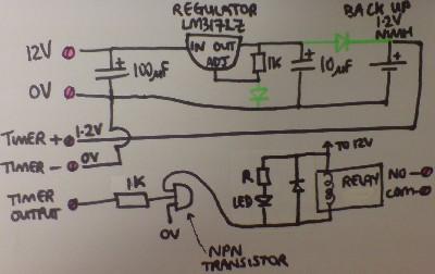
Most supermarkets today offer plug-in mains-powered digital programmable timers. These devices are designed to automatically turn lights on and off, activate washing machines while the user is away, and more. Prices start at around £5 ($10), and these products...
If a page name is not selected by pressing the button, the previously selected page name continues to be used. The value is stored in EEPROM and may be changed at any time. When the unit is first powered...
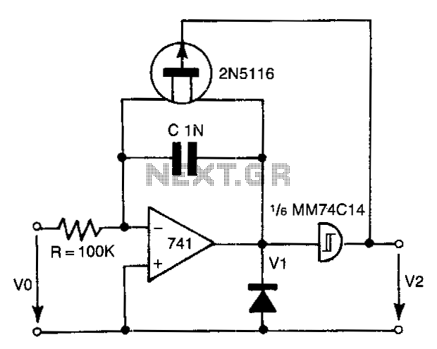
The 741 operational amplifier integrator signal is input into the Schmitt trigger of an inverter. When the signal reaches the positive-going threshold voltage, the inverter's output switches to zero. This output directly controls the FET switch. With a gate...
This circuit is a dual voltage regulated power supply, +12, -12, 0 volt. It uses the 7812 and 7912 regulators. You need a 18VCT, 1A transformer at input. More: Caution: Input / Ground are reversed between the 7812 and...
A voltage-controlled oscillator (VCO) is an oscillator whose frequency is regulated by a voltage signal. The VCO discussed here can generate both triangular and square wave outputs. The control voltage can be adjusted between 5 mV and 5 V,...
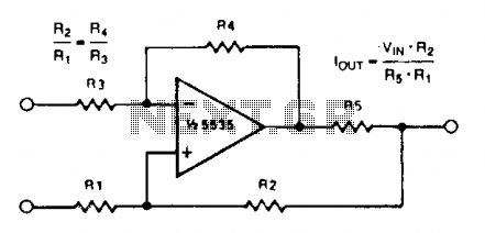
A simple voltage-to-current converter is illustrated. The output current is given by 0t or Vjn/R. For negative currents, a PNP transistor can be employed, and for improved accuracy, a Darlington pair can replace the transistor. With meticulous design, this...