
high performance sawtooth generator

The sawtooth generator circuit described operates by utilizing a combination of active and passive components to produce a linear ramp waveform. The core of the circuit consists of an operational amplifier (IC1) configured as a voltage-controlled current source, which is essential for controlling the charging and discharging cycles of capacitor C1. The resistor R1 plays a crucial role in setting the charging current, while Q1, as part of the current source, ensures that the output remains stable and responsive to voltage changes.
During operation, capacitor C1 discharges through the current Io until its voltage falls below the threshold of 1.66V. This triggers a transition in the output of the comparator IC2A from a low state to a high state (5V), initiating the charging phase of C1. The charging process is governed by the diode-connected transistor Q2, which allows current to flow into C1, thereby increasing its voltage until it reaches 3.33V. At this point, the comparator IC2A detects the voltage level and switches its output back to a low state (ground), completing one cycle of the sawtooth waveform.
The frequency of the output waveform is directly influenced by the values of C1 and R1. By adjusting these components, the designer can manipulate the timing characteristics of the circuit, allowing for a wide range of frequencies to be generated. However, it is important to consider the limitations imposed by the slew rate and settling time of the comparator IC2A, as these factors can affect the linearity and stability of the output waveform.
In summary, this sawtooth generator circuit is a cost-effective solution for generating a sawtooth waveform and an auxiliary square wave. Its design allows for frequency modulation, making it suitable for applications where frequency sweeping is required. The careful selection of components and their values is critical for achieving the desired performance and operational range of the generator.This is a design for sawtooth generator circuit. The advantage of this circuit is low cost and produces an auxiliary square wave at the same frequency. This circuit can be used to sweep the frequency of another generator. This is the figure of the circuit. A voltage-controlled current source is formed by IC1 with R1 and Q1. The C1 is discharged by current Io until it`s voltage is less than 1. 66V. It will swing its output to 5V and trips the IC2A comparator. The C1 is charged by current through the diode-connected transistor (Q2) until its voltage reaches 3. 33V, so the IC2A output to swing back to ground. The output frequency is determined by : We can set the fOUT as high as desired by adjusting the values of C1and R1, subject to the limitations of comparator IC2A`s slew settling and rate time.
The frequency range over which it can operate determined by generator`s linearity. 🔗 External reference
Related Circuits
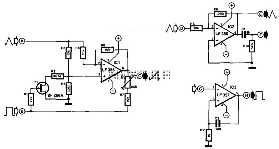
Simple function generators typically produce sinusoidal, rectangular, and triangular waveforms, but rarely generate sawtooth waveforms. The circuit depicted in Fig. 21-4(a) generates a sawtooth signal from rectangular and triangular signals. The quality of the sawtooth output is influenced by...
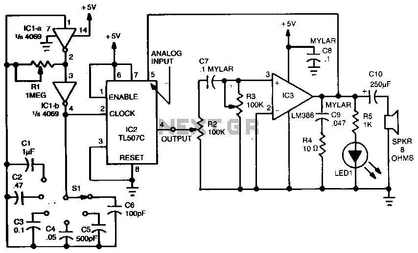
A variable dock-pulse generator consists of two sections of IC1, which is a 4069 CMOS hex inverter, along with resistor R1, switch S1, and capacitors C1 through C6. By adjusting R1 and switching one of the capacitors into the...
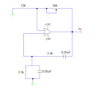
An operational amplifier-based sine wave generator circuit, commonly known as a Wien bridge oscillator, is recognized for its simplicity and stability. The Wien bridge oscillator connects the Wien bridge circuit between the amplifier's input and output terminals. The bridge...
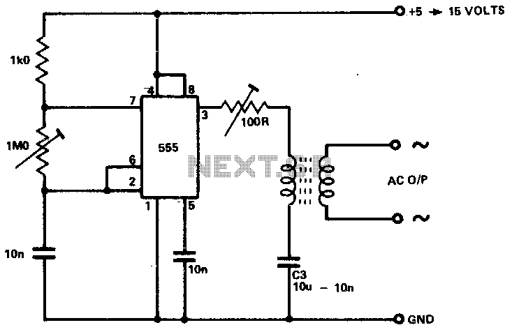
The circuit is designed to supply power for portable Geiger counters, dosimeter chargers, high resistance meters, and similar devices. The 555 timer integrated circuit (IC) operates in its multivibrator mode, with the frequency adjusted to optimize the characteristics of...
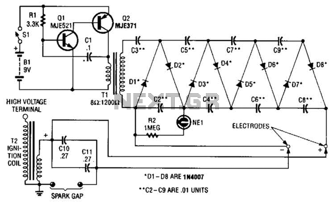
This circuit employs a transistor oscillator and a voltage multiplier to charge capacitors CIO and CI1 to a high voltage. When the spark gap breaks down, T2 generates a high-voltage pulse through the discharge of capacitors CIO and CI1...
This program uses an 8 bit DAC along with a 16F84 PIC microcontroller to generate a keyed sine wave. The 16F84 uses an RC clock which can be varied (with a suitable potentiometer) to allow a variable frequency control...