
High-Power Car Audio Amplifier

The circuit described pertains to a stereo amplifier with a bridge configuration. The setup requires specific modifications to optimize performance and ensure proper functionality. The installation of jumpers JU2 and JU4 is necessary to enable the bridge mode, which enhances the amplifier's power output capabilities. The removal of J1 and RIO is a crucial step in configuring the circuit for bridge operation.
Resistor modifications include replacing R13 with a jumper wire, which effectively bypasses that component, and substituting R15 with a 4.53 kΩ, 1% tolerance resistor. Additionally, R14 should be replaced with a 13 kΩ, 1% tolerance resistor, ensuring precise resistance values are maintained for stability and performance. The instruction to cut the foil between the pads from RH and ground is essential for isolating the circuit paths, preventing unintended connections that could lead to performance degradation.
The input configuration transforms into the left channel input, which is critical for stereo sound separation. Outputs from both the left and right channels are specified, allowing for a balanced audio performance. This amplifier is capable of delivering 60 W RMS into an 8-ohm load and 100 W RMS into a 4-ohm load, making it suitable for various audio applications.
The LM12C1 operational amplifier requires a line level input of approximately 300 mV for optimal performance. For full power output, a dual polarity supply of ±35 V is necessary. This power supply can be obtained using a DC-DC converter, which can efficiently convert available voltage levels to meet the amplifier's requirements. Overall, this configuration and the specified components ensure robust audio amplification suited for high-fidelity applications. NOTE: FOR BRIDGE CONFIGURATION: t install jumpers ju2 and ju4 2.remove j 1)3 3.remove rio 4replace r13 with jumper wire 5replace ri5 with 4.53k ohm 1% 6. replace r14 with 1 13k ohm 1% 7 cut foil between pads from rh and ground 8.input becomes left channel input 9.take ( output from left output 10 takf output from right output This stereo amp will supply 60 W rms into 8 or 100 W rms into 4 . Notice that the LM12C1 line level (about 300 mV) into 5 . A ±35-V supply is required for full power output. Power can be obtained from a dc-dc converter.
Related Circuits
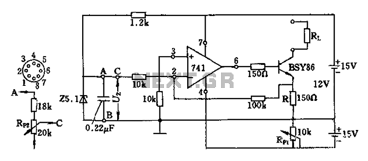
The Darlington transistor circuit BSY86 produces a large output current, with a maximum limit of 150 ohms. The output current is adjustable via resistor R and the RP1 potentiometer, maintaining constancy regardless of the load resistance Rl. The potentiometer...
A dual benefit for battery-powered portable devices is provided by Class D audio amplifiers. They produce much less power dissipation than their linear counterparts. Class D audio amplifiers, also known as switching amplifiers, are designed to achieve high efficiency and...
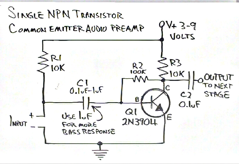
The biasing calculations for collector feedback common emitter amplifiers had not been previously addressed, particularly for a simple one-transistor NPN preamplifier built by Dino. Confusion arose regarding the role of resistor R1 in the schematic, which appeared to serve...
This circuit is primarily designed to provide a microphone input for standard home stereo amplifiers. Utilizing a battery supply effectively eliminates the risk of low-frequency hum interference from mains power, simplifying the connection to the amplifier by removing the...
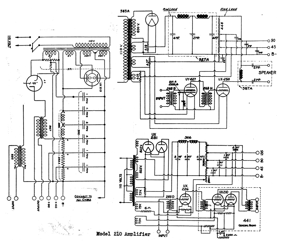
The schematic shows a valve / tube audio power amplifier and a type 390 Rectron B eliminator. The presented schematic illustrates a valve or tube audio power amplifier, which utilizes vacuum tubes to amplify audio signals. This type of amplifier...
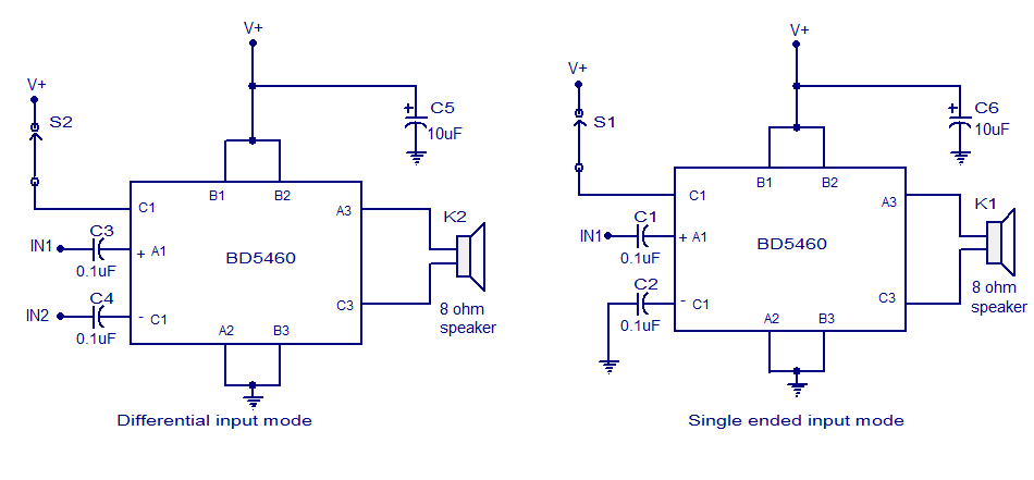
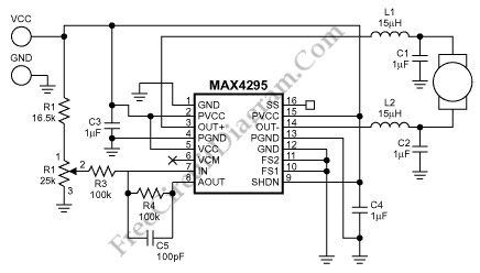
The BD5460 is a low power Class D amplifier that can be utilized in low power applications such as handheld audio devices. The BD5460 does not require an LC filter at the speaker output and can be powered by...