
High Speed NiCd Charger for R/C

The described charging system is designed to efficiently handle NiCd (Nickel-Cadmium) battery packs, specifically targeting configurations such as the 7-cell RC2000 and the 8-cell RC2400 or CP2400SCR. The charging process is optimized to complete within 14 to 17 minutes, respectively, which is crucial for applications requiring quick turnaround times.
During the charging process, two primary phenomena influence the thermal behavior of the NiCd cells. First, the internal resistance of the cell generates heat as the charging current flows through it, a phenomenon quantified by the I²R losses, where 'I' represents the charging current and 'R' represents the internal resistance. This heat generation is an essential factor to monitor, as excessive heat can lead to cell degradation or failure.
Simultaneously, the electrochemical process occurring within the NiCd cells is endothermic. This means that the chemical reaction involved in charging absorbs heat, acting as a cooling mechanism during the initial phase of charging. However, once the cell reaches full charge, this endothermic reaction ceases, and any continued application of current can lead to an increase in temperature. The implications of this are significant; if the charging current remains constant, the cell will begin to heat up due to the I²R losses without the counteracting cooling effect of the endothermic reaction.
For example, if a charging current of 10 Amps is sustained, the resultant heat buildup can be considerable, necessitating careful thermal management strategies to prevent overheating. It is essential to incorporate temperature monitoring and current regulation features in the charging circuit design to ensure that the cells are charged safely and efficiently, prolonging their operational lifespan and maintaining performance.
Overall, the charging system must balance the rapid charging capabilities with the thermal management of the cells to ensure optimal performance and safety during operation.It can safely charge a 7-cell RC2000 pack in about 14 minutes, and an RC2400 or CP2400SCR pack in about 17 minutes. As a NiCd cell is being charged, two things happen which affect its temperature. Due to resistive losses within the cell, some of the charging current is converted to heat (I2R losses).
At the same time, the chemical reaction that takes place during NiCd charging absorbs heat (i.e. it`s an endothermic reaction). Once a cell is fully charged, the endothermic chemical reaction stops. This means that continued charging current, no matter how low, will cause the cell to heat up. Higher currents will heat the cell up faster. At 10 Amps for example, the cell will heat 🔗 External reference
Related Circuits
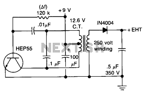
This circuit will generate approximately 300 volts DC at a very low current, sufficient for a GM tube. Caution is advised with the output. The described circuit is a high-voltage DC power supply designed to provide approximately 300 volts, which...
This circuit incorporates a datasheet-compliant trigger signal, reversed polarity protection, an optional test button, and the capability for battery operation. It utilizes either the U1 L601E3 or MAC97A8 triac, rated for 400 V and 1 A. When U1 is...
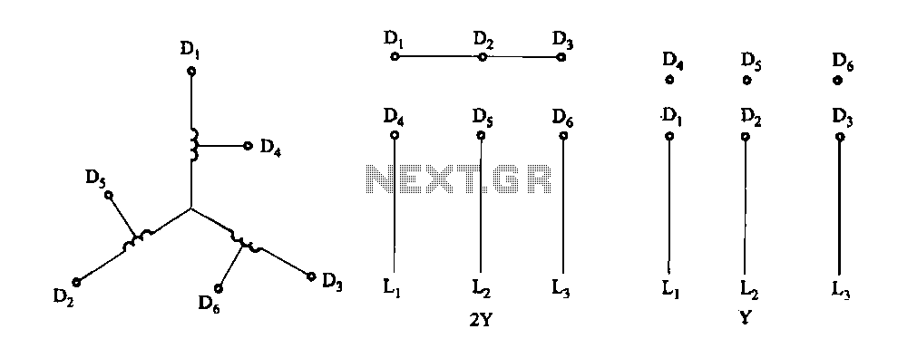
Figure 3-100 illustrates the lead wiring diagram for the stator windings of a two-speed motor configured in a 2Y/Y connection. The two-speed motor stator wiring diagram depicted in Figure 3-100 provides a clear representation of the electrical connections required for...
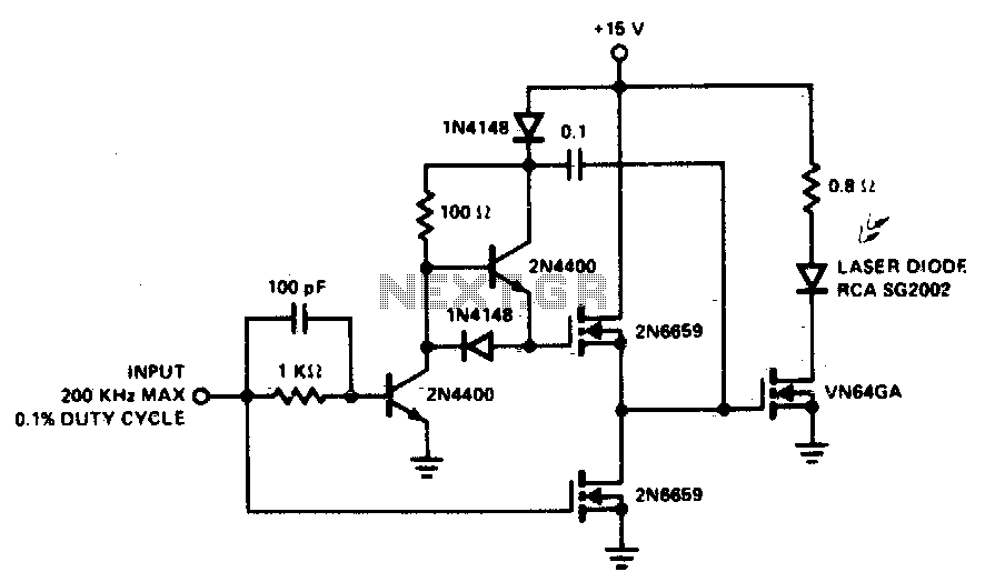
A faster driver can supply higher peak gate current to switch the VN64GA very quickly. The circuit uses a VMOS totem pole stage to drive the high power switch. The described circuit employs a high-speed driver to enhance the switching...
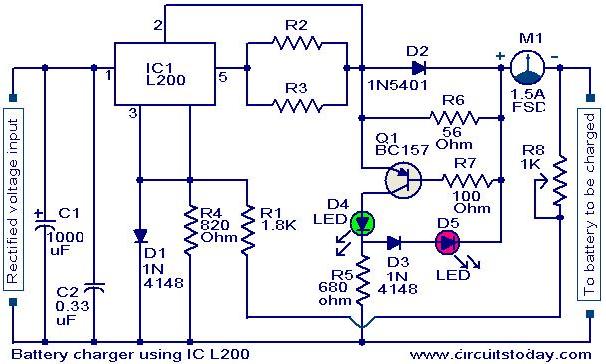
A simple battery charger circuit with reverse polarity indication is presented here. The circuit utilizes the L200 integrated circuit (IC), which is a five-pin variable voltage regulator. The charging circuit can be powered by DC voltage from either a...
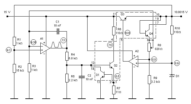
10V high-stability voltage source model power supply. Refer to the specified page for an explanation regarding the associated circuit diagram. The 10V high-stability voltage source is designed to provide a reliable and consistent output voltage, making it suitable for various electronic...