
High Voltafe Generator

The described circuit is a series voltage regulator that utilizes a combination of transistors and a zener diode to maintain a stable output voltage. The primary control element, Q900, is responsible for regulating the output voltage by adjusting the current flow through the load based on feedback from the output voltage.
Q901 serves as a driver transistor, amplifying the control signal from Q902, which functions as the error amplifier. The error amplifier compares the output voltage to a reference voltage established by the zener diode (ZD900). This configuration allows for precise voltage regulation, as any deviation in the output voltage is detected by the error amplifier, prompting Q900 to adjust its conduction accordingly.
The inclusion of T900 indicates that the circuit may also involve a transformer, which plays a crucial role in transferring energy between circuits while providing isolation and voltage scaling. The magnetic coupling provided by T900 ensures that changes in the high voltage (H.V.) side of the circuit are reflected in the lower voltage outputs. This interdependence means that any fluctuation in the high voltage directly impacts the stability of the other output voltages, necessitating careful design to ensure that all outputs remain within desired parameters.
Overall, this series regulator design is effective for applications requiring stable voltage outputs across multiple circuits, particularly where high voltage levels are involved. The feedback mechanism and the use of magnetic coupling are key features that enhance the reliability and performance of the voltage regulation process.This is a series regulator with Q900 being the control ele- ment, Q901 a driver, and Q902 an error amp. ZD900 forms the emitter reference voltage source. Since the generated high voltage and other voltages are linked by means of the magnetic field of T900, any change in H.V.
will be reflected back to all of the other voltages. 🔗 External reference
Related Circuits
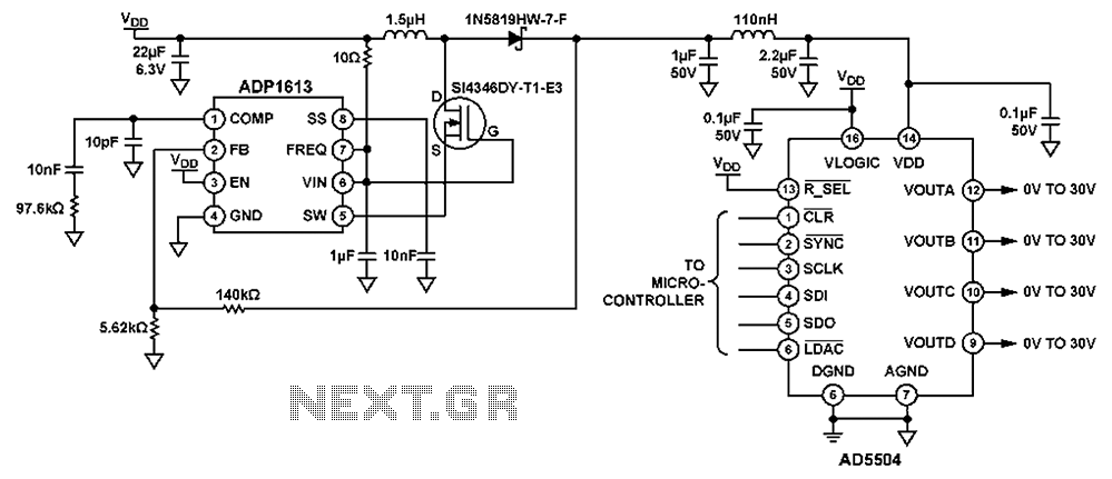
The circuit depicted in FIG. 1 generates a high-voltage signal for controlling the capacitance of barium strontium titanate (BST) capacitors. By applying voltages of V and 3V to the appropriate terminals, the capacitance of the BST can be modified....
A high voltage power supply DC converter that operates between 3V to 500V has been suggested for use with Geiger tubes. However, during simulation, the output remained at nearly 9V, which matches the input voltage. The schematic drawn has...
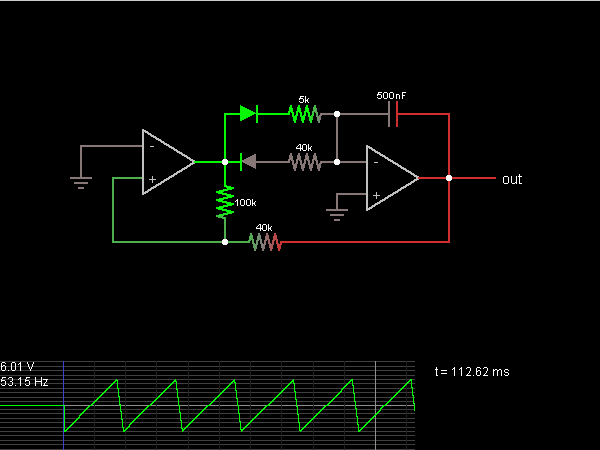
This is the sawtooth wave generator circuit diagram, accompanied by a detailed explanation of its operational principles. An electronic circuit simulator is available to assist in designing the sawtooth wave generator circuit and simulating it online for enhanced understanding. The...
This is a simple square wave generator circuit constructed using the IC 74LS00, capable of producing square wave signals with frequencies ranging from 20 Hz to 1 MHz. The circuit exhibits sufficient stability for most applications. The output frequency...
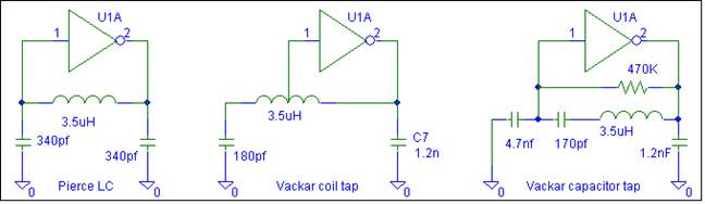
This oscillator does not require biasing components. Only an inductor and various matching or tuning capacitors are needed to set the operating frequency. The active component is the 74HCU04 hex inverter, with only one of the six inverters necessary...
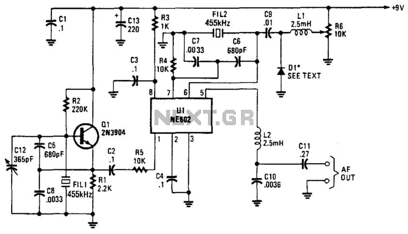
Q1 is a fixed oscillator operating at 455 kHz. U1 is a mixer with its own internal oscillator running at 45.5 kHz. FIL1 and FIL2 are Murata CSB455E filters or equivalent. D1 is a varactor diode (an IN4002 used...