
HIGH VOLTAGE NEGATIVE ION GENERATOR

The circuit employs a modified flyback transformer, which is known for its ability to generate high voltages efficiently. The flyback transformer operates by storing energy in its magnetic field during the flyback period of the horizontal scan in a television set. In this application, it is adapted to produce a higher output voltage than typical television applications.
The voltage multiplier is a crucial component in this circuit, as it steps up the voltage produced by the flyback transformer. This is typically achieved through a series of capacitors and diodes arranged in a configuration that allows for the accumulation of voltage. The diodes prevent backflow of current, while the capacitors store charge, effectively multiplying the voltage output.
The output voltage, which can vary between 9 kV and 14 kV, is then directed to a discharge needle. This needle serves as an ion emitter, where the high voltage creates a strong electric field that ionizes the surrounding air, resulting in the production of negative ions. These ions can have various applications, such as improving air quality or in certain industrial processes.
The design of the circuit must ensure that all components can handle the high voltages involved, particularly the voltage multiplier and the discharge needle. Proper insulation and safety measures should be implemented to prevent electrical hazards. Additionally, the circuit may require a suitable power supply to energize the flyback transformer, which must be capable of providing the necessary input voltage and current for stable operation.
Overall, this circuit exemplifies the use of high-voltage technology in generating negative ions, leveraging the principles of electromagnetic induction and voltage multiplication effectively.A modified B/W TV flyback transformer is used in this circuit with a voltage multiplier to produce 9- to 14-kV negative voltage. This is connected to a discharge needle to produce negative ions. 🔗 External reference
Related Circuits
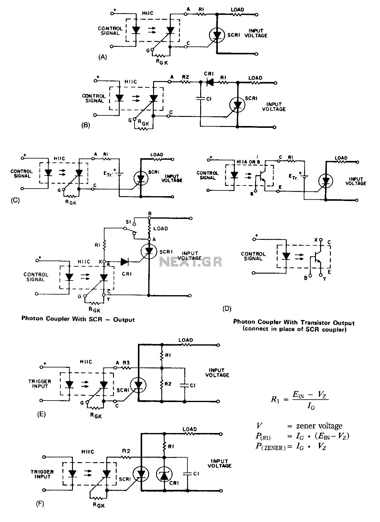
A basic circuit to trigger a silicon-controlled rectifier (SCR) is illustrated in Figure 67-1A. This circuit has the limitation that the blocking voltage of the photonic coupler output device dictates the circuit's blocking voltage, despite the SCR's higher voltage...
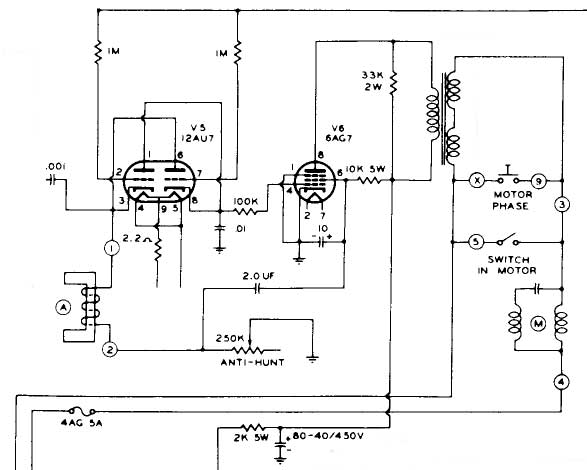
The motor control chassis lacks a coaxial input, raising doubts about the presence of composite sync, particularly given the length of the cables (5 or 6 feet), which may eliminate the possibility of a sync pulse for the red...
Building your own Zapper. It requires one capacitor of 1 microfarad (C2), preferably unpolarized to eliminate concerns regarding positive and negative terminals. If a polarized capacitor is used, the longer leg indicates the positive side; refer to the schematic...
.png)
The one-touch turn signal (OTTS) module enhances the functionality of the turn signal lever by adding a mode where a single touch makes the indicators blink for a certain number of times. This behavior is also known as lane...
These units can be useful as a short-range, single-channel remote-control. When the pushbutton in the transmitter circuit is briefly activated, the LED D1 in the receiver illuminates and an optional beeper or relay can be operated. Circuit operation is...
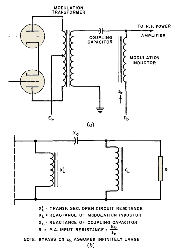
Wave-filter principles are utilized in various circuits beyond filters, such as in the design of modulation transformers for high-level amplitude-modulated radio transmitters. Some of these transformers are quite large. In plate-modulated power amplifiers, the modulator power necessary for achieving...