
Magnetic-Radiation Remote-Control

The circuit consists of two main sections: the transmitter and the receiver. The transmitter employs a simple pushbutton switch connected to an oscillator circuit that generates a 35KHz signal. This oscillator can be built using a 555 timer IC configured in astable mode or using a basic transistor oscillator circuit. When the pushbutton is pressed, the oscillator activates, transmitting a modulated signal at 35KHz.
The receiver section is designed to pick up the 35KHz signal. It features a high-gain amplifier, typically constructed using operational amplifiers or transistors, configured in a two-stage arrangement to boost the weak signal received by the antenna. The output of this amplifier is fed into a frequency-voltage converter, which translates the frequency of the incoming signal into a corresponding voltage level. This conversion is crucial for controlling the subsequent DC load driver, which can activate an LED, beeper, or relay.
The LED D1 serves as a visual indicator, illuminating when the signal is successfully received and processed. If a beeper or relay is included in the circuit, it can be powered on by the output from the DC load driver, allowing for additional functionality such as sound alerts or controlling larger loads.
The overall design emphasizes simplicity and efficiency, making it suitable for various applications in remote control systems, such as garage door openers, alarm systems, or simple wireless switches. The non-modulated nature of the carrier frequency simplifies the design but may limit the range and robustness against interference compared to more complex modulated systems.These units can be useful as a short-range, single-channel remote-control. When the pushbutton in the transmitter circuit is briefly activated, the LED D1 in the receiver illuminates and an optional beeper or relay can be operated. Circuit operation is based on a non-modulated 35KHz frequency carrier transmitter, and on a high-gain two-stage 35KHz amplifier receiver, followed by a frequency-voltage converter and DC load driver.
🔗 External reference
Related Circuits
This unit serves as a short-range, single-channel remote control. When the pushbutton on the transmitter circuit is briefly activated, the LED D1 in the receiver illuminates, and an optional beeper or relay can be triggered. The circuit operates on...
This transmitter emits an FM signal within the 88 to 108 MHz frequency range, featuring a tone of 19 kHz. This tone can activate the FM MPX pilot carrier indicator, allowing interfacing with external devices. L4 is designed for...
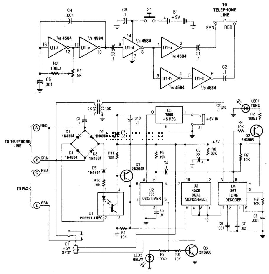
This system uses a transmitter operating at approximately 100 kHz to control a remote receiver. A line splitter can connect the transmitter to the active telephone line. The transmitter is a CMOS oscillator equipped with output buffer stages to...
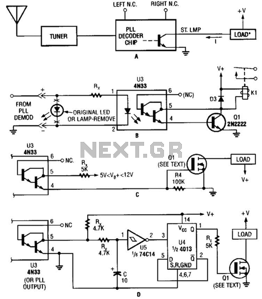
Several possible interface circuits are presented for use with a remote-control transmitter. The circuit labeled A demonstrates a typical FM stereo MUX decoder with a load connected directly to the open-collector output of a TA7343 PLL. The circuit labeled...
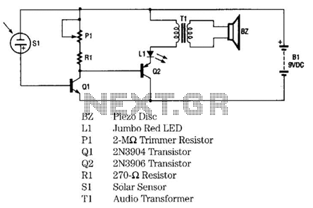
The infrared remote-control tester employs a sensitive PN-type solar sensor directly connected to a Darlington amplifier composed of transistors Q1 and Q2. Biasing is achieved through resistor R1 and PI, a variable resistor that functions as a sensitivity control....
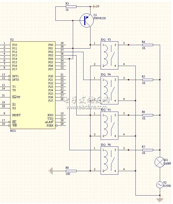
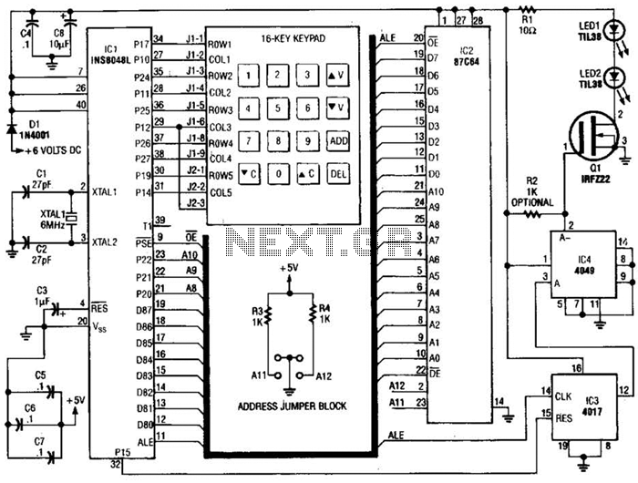
This system is a control system based on a single-chip computer that allows for remote operation of lighting. The scheme primarily addresses the transmission and reception of signals, as well as program manipulation of various signals once they are...