
LED pulse width modulator

The described PWM modulation technique for high-power LEDs and laser pointers utilizes a square wave signal to control brightness levels effectively. The circuit operates by generating a square wave with varying duty cycles, which translates into different output voltages. The PWM frequency is crucial; it is set significantly higher than the audio signal frequencies to ensure that the resulting output voltage is a smooth representation of the desired analog signal. The output stage typically includes a low-pass filter to average out the PWM signal, providing a steady DC voltage that corresponds to the duty cycle.
In practical applications, the design should incorporate a microcontroller or a PWM generator capable of high-resolution timing to ensure accurate duty cycle representation. A common choice may be a 10-bit resolution, allowing for fine control over brightness levels. The microcontroller's clock frequency should be carefully selected to maintain the necessary timing precision, which could involve using a high-frequency oscillator to achieve the desired PWM frequency.
For driving laser pointers, additional circuitry must be integrated to manage voltage and current levels safely. This might involve using operational amplifiers configured as voltage followers or current regulators to protect the laser from damage while ensuring optimal performance.
Furthermore, the optical receiver's bandwidth must be considered in the circuit design. If the receiver is capable of responding to PWM frequencies, it may introduce unwanted artifacts in the audio signal chain. Therefore, selecting receivers with limited bandwidth characteristics is advisable to avoid complications with downstream audio processing.
Overall, this PWM modulation approach provides a versatile method for controlling high-power LEDs and laser pointers, allowing for efficient brightness modulation while minimizing distortion and ensuring safe operation within electronic systems.Fairly early on in my work with high-power LEDs such the Luxeon 1 and 3 watt devices I considered that PWM (Pulse Width Modulation) techniques would be an interesting means of modulation the LED. In theory, this should be capable of producing the lowest distortion modulation on an LED because the linearity of the LED`s "Current-versus-Luminous Out
put" curve would be irrelevant: The apparent brightness would be integrated by the receiver to produce a voltage proportional to the duty cycle. In addition to high-power LEDs, this unit is also suitable for driving inexpensive laser pointers, provided that suitable circuitry (e.
g. voltage/current regulation) is used with the laser pointer. In other words, it will NOT safely drive a laser pointer directly! For a "steady state" DC output (that is, no waveforem being generated) a 50% duty cycle square wave is generated at a frequency several times higher than the highest-frequency component in the audio to be reproduced. While this frequency could theoretically be as low as just twice the highest audio frequency, it is usually several times higher than that to simplify lowpass filtering and to cut costs.
To increase the output voltage, the duty cycle of this square wave is increased, with 100% being "full on. " Conversely, to decrease the voltage, the duty cycle would be decrease, down to 0% being completely off.
In reality, most PWM circuits avoid getting too close to either 0% or 100% as either extreme would produce objectionable "hard" clipping. The PWM output is filtered to average out the square wave, the ultimate result being a voltage that is directly proportional to the duty cycle of the original square wave.
As it turns out, the linearity of a PWM generator could, in theory, be absolutely perfect as the duty cycle is timed precisely using digital counters, but what is necessary is that there be enough timer resolution in order to provide the needed resolution of duty cycle. Take, for example, a 10 bit PWM converter. Because 10 bits represents 1024 steps, it would be necessary that the original timing clock be 1024 times that of the sampling rate.
If, for example, our original clock were 20 MHz, one 1024th of that would be 19. 53125 kHz. In practical terms, it is usually desirable the frequency response of the circuits in a typical optical receiver not be able to respond at the PWM frequency, with the resulting "smoothing" being a voltage that is very close to the original analog signal applied to the modulator as depicted in Figure 1. This technique usually works as more-sensitive optical receivers designed for speech bandwidth (and/or their following amplifier stages) don`t have the frequency response characteristics necessary to reproduce the original PWM waveform.
Some caution should be exercised, however: If the optical receiver does have the bandwidth to recover the PWM signal - or if there is a reduced (but still sufficient) response of the audio chain at the PWM frequency - this could play havoc with downstream audio devices in several ways: The audio amplifier may be capable of amplifying the PWM signal, robbing power from the audio-frequency components. In this situation, the audio amplifier is putting out its normal power, but some of it may be wasted at the PWM frequency and be inaudible to human hearing.
In this case, the audio amplifier may overload at lower-than-normal volume levels. Aliasing artifacts on digital audio devices. Computer sound cards and digital audio recorders may not be able to sufficiently filter the PWM frequency from their inputs and this may result in odd aliasing artifacts, which may include noise, distortion, or odd mixing effects. While the above are possibilities, I have not experienced these effects when using my Version 3 optical receiver (with the lowpass filter switched out, or even the "simplified" versions) with digital audio devices - but the fact that this receiver is
🔗 External reference
Related Circuits
A coil is wound around a non-conductive tube, which serves as the barrel of the coilgun. The tube must be made from a non-conductive material, such as plastic, to prevent the coil's magnetic field from canceling itself out within...
If the reader arrived here via Google, they may have encountered other circuits for high-power LED driving that include many components such as inductors, operational amplifiers, various regulator ICs, transistor feedback networks, and microcontrollers. While those circuits tend to...
Several 1.5 V LED flasher circuits can be found online, and four of them are presented here. The flasher circuits operate on a single 1.5 V power supply. The design of a 1.5 V LED flasher circuit typically involves a...
A simple white LED driver schematic can be created using the EL7513 constant current boost regulator, which is specifically designed for driving white LEDs. This driver can manage 4 LEDs in series or up to 12 LEDs in a...
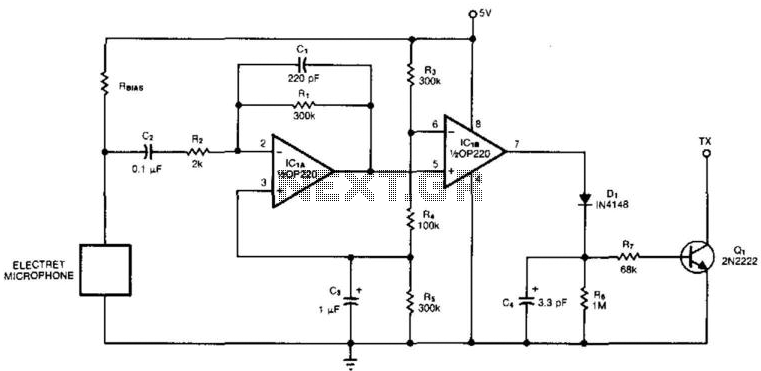
An electret microphone feeds a bandpass filter circuit (IC1A), which subsequently drives a comparator. This comparator activates Q1, a switch that conducts when audio signals from IC1B cause D1, C4, R6, and R7 to bias it ON. The circuit begins...
This circuit is suitable for a small office or home environment. It can also be adapted to use a combination lock or keypad for setting and resetting. The described circuit functions as a security system tailored for small office or...