
Pulse Induction Metal Detector

This project involves the design of a stable electronic unit that can be configured in three distinct ways using coils. The stability of the unit is a critical feature, ensuring consistent performance across various applications. The use of coils in different configurations allows for flexibility in operation, which can be tailored to specific requirements or preferences.
The inclusion of a piezo buzzer enhances the functionality of the unit, providing audible feedback or alerts when the circuit is activated. Piezo buzzers are known for their efficiency and reliability, making them suitable for integration into various electronic projects. The connection of the buzzer to the circuit should be done in such a way that it does not interfere with the primary operation of the unit. Typically, the buzzer can be connected to a digital output pin of a microcontroller or a transistor switch that is activated under certain conditions dictated by the circuit's logic.
When constructing the circuit, it is essential to ensure that all components are rated for the voltages and currents they will encounter. Proper grounding and power supply considerations must also be taken into account to avoid issues related to noise or instability. Additionally, the layout of the circuit should minimize interference and allow for easy access to the configuration options for the coils.
Safety precautions should be observed throughout the assembly process, as the project is to be built at the individual's risk. It is advisable to test each configuration of the coils separately to ascertain their performance before integrating them into a single unit. This systematic approach will help in identifying any potential errors or issues that may arise during operation.This project is offered totally Free for those who are interested in it. I have tried to make this article as complete as possible, but I will Not assume any lilability for any "Errors or Omissions" in this article. If Needed, I will attempt to help you as much as possible with any problems. However I have no control of your abilities or skills, so build it totally at your own risk! This unit is Extremely Stable, and features three possible configurations with the coils, as listed below. I can now supply a small Pizo Buzzer that works quite well on this unit. Well the reason why you can`t detect it is because the conducti 🔗 External reference
Related Circuits
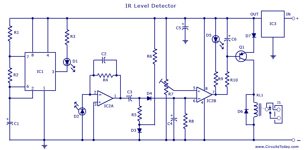
An infrared (IR) sensor or detector circuit diagram utilizing a 555 integrated circuit (IC), primarily employed as a water level or liquid level sensor and proximity detector circuit. The described circuit employs a 555 timer IC configured in a monostable...

The primary component in the circuit is the SRI, a TGS812 toxic gas sensor produced by Figaro Engineering Inc. This gas-sensitive semiconductor functions as a variable resistor when exposed to toxic gases, resulting in a decrease in electrical resistance...

This application utilizes a timer configured for astable (free-running) operation, with a modulating signal applied to the control voltage terminal. The pulse position changes in accordance with the modulating signal, as both the threshold voltage and the time delay...
The second 555 timer was configured as a monostable circuit, commonly referred to as a one-shot since an output pulse only occurs if there is a trigger on the input. When this timer is triggered, the potentiometer in the...

This circuit is a constant current protection type that limits the output current to a specific value in cases of over-current and short-circuit conditions. When the output current exceeds this limit, the output voltage decreases. The CW200 power management...

Connected in this manner, an LM317 1-A adjustable-voltage regulator can be utilized to control the speed of a miniature DC motor or to adjust the brightness of a small lamp. The circuit achieves this by modulating the pulse width,...