
Negative Voltage From A Positive Supply

The circuit employs a 555 timer configured in astable mode to generate a continuous square wave output. The frequency of the square wave can be adjusted by selecting appropriate resistor and capacitor values connected to the timer. The output from the 555 timer is then fed into a voltage-doubling circuit, typically composed of diodes and capacitors arranged in a charge pump configuration.
In the voltage-doubling stage, the positive half of the square wave charges a capacitor through a diode, while during the negative half, the charged capacitor is connected in series with the input voltage, effectively doubling the voltage across the load. This setup allows for the generation of a negative voltage that is close to the magnitude of the positive supply voltage.
The output current capability of the circuit, which can reach between 20 to 30 mA, is influenced by factors such as the load resistance, the efficiency of the voltage-doubling circuit, and the specifications of the components used. Proper selection of the capacitors and diodes is crucial to optimize performance and ensure that the current output meets the desired requirements for the application. Additionally, filtering may be required to reduce ripple voltage and stabilize the output voltage for sensitive applications. By using a 555 timer to generate a square wave and voltage-doubling the output, a negative voltage that is almost equal to the positive supply can be obtained. The current available is up to 20 to 30 mA or so, depending on the regulation and voltage needed.
Related Circuits
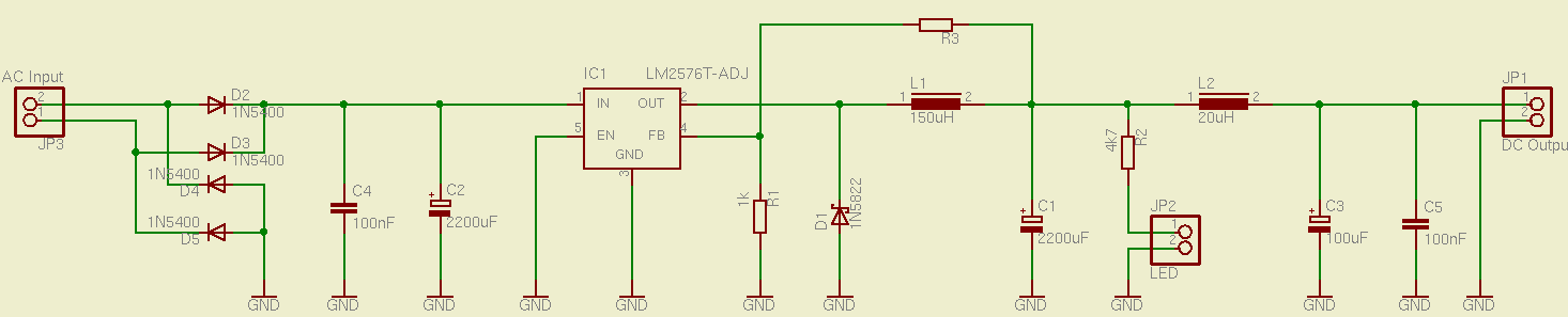
This is a simple and effective switched mode power supply (SMPS) designed to power an LCD monitor. It requires 20V at 2.3A, but the power supply unit (PSU) output voltage can be adjusted in the range of 1.2V to...

An electronic rectification circuit that avoids the use of large, heavy, and expensive electrolytic capacitors by utilizing an active transistor in a gyrator configuration. To minimize excess ripple output on a power supply feeding a heavy load, a large...
In certain scenarios, a 5-V supply voltage is available, but a portion of the circuit requires a lower supply voltage. The TPS62000 series voltage regulator from Texas Instruments is an appropriate solution for applications with a current consumption of...
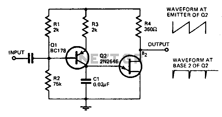
With the component values shown, the oscillator has a frequency of 8 kHz. When an input signal is applied to the base of Q1, the current flowing through Q1 is varied, thus affecting the time required to charge C1....
This simple and inexpensive circuit can produce a dual (positive and negative) voltage from a single supply input. It is therefore extremely useful for powering opamp and other circuits that require a dual voltage from a single battery. The...
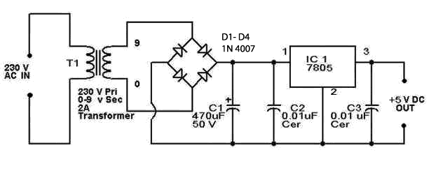
5V regulated power supply circuit, 5V power supply circuit, regulated power supply circuit diagram. The 5V regulated power supply circuit is designed to provide a stable output voltage of 5 volts, which is essential for powering various electronic devices and...