
homebrew rf circuit design

Yo3dac is known for innovative approaches in the realm of radio frequency (RF) circuit design, particularly within the homebrew community. The RF circuit designs discussed are typically focused on enhancing communication capabilities, optimizing signal integrity, and improving overall performance in amateur radio applications.
Key components often featured in these designs include oscillators, amplifiers, and filters, which are essential for generating and processing RF signals. Oscillators may be implemented using various configurations, such as Colpitts or Clapp oscillators, to achieve stable frequency generation. Amplifiers, often based on bipolar junction transistors (BJTs) or field-effect transistors (FETs), are crucial for boosting signal strength to ensure reliable transmission and reception.
Filters play a significant role in RF circuits by allowing specific frequency ranges to pass while attenuating unwanted signals. Common filter topologies include low-pass, high-pass, band-pass, and notch filters, each serving distinct purposes in signal conditioning.
The integration of microcontrollers or digital signal processors (DSPs) can further enhance these designs, enabling advanced functionalities such as frequency synthesis, automatic gain control, and digital modulation techniques. Additionally, the use of software-defined radio (SDR) principles allows for flexibility in design and operation, accommodating various communication protocols and standards.
Overall, the homebrew RF circuit design ideas from Yo3dac reflect a commitment to innovation and community sharing, providing valuable insights and practical solutions for enthusiasts and professionals alike in the field of RF engineering.This time on we Will Share About Yo3dac Homebrew Rf Circuit Design Ideas Latest Info at Onmilwiki.. 🔗 External reference
Related Circuits
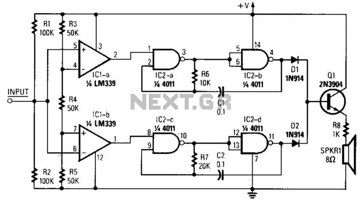
The circuit designed for distortion measurements eliminates the fundamental frequency of 1 kHz, enabling the assessment of the residual harmonic levels. Initially, a true RMS meter is employed to measure the 1-kHz input level (E^) by positioning the switch...
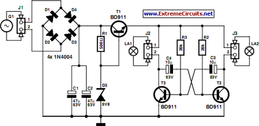
On a mountain bike, a common issue with traditional flashing LED lights from stores is the frequent problem of flat batteries and lights detaching. As an electronics student, a better solution was sought. A front wheel with a built-in...
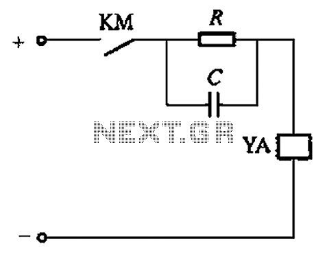
Both resistive and capacitive types of capacitor discharge circuits utilize strong excitation methods. The capacity of capacitor C influences the duration of strong excitation. The operation of a capacitor discharge circuit involves the release of stored electrical energy from a...
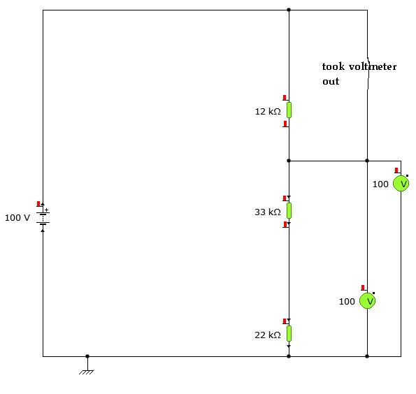
A user is utilizing YENKA software to diagram circuits but is experiencing confusion regarding the voltage calculations in a basic series circuit, as illustrated in the attached image. In a basic series circuit, components are connected end-to-end, forming a single...
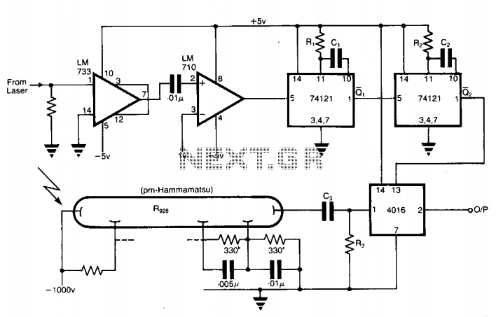
The application involves observing the light pulse emerging from a thick specimen after transillumination by a laser pulse. Pulses derived from the laser source are amplified using a Video Amplifier LM733. The reference level is set to 1 V...
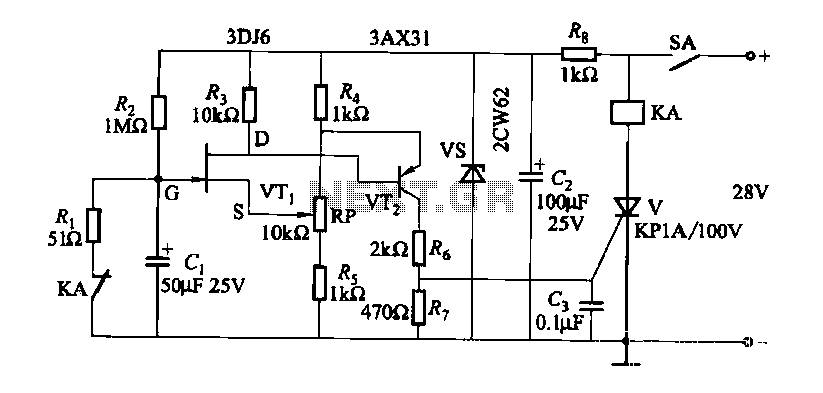
FET relay circuit 2 is essentially a JS-20 time relay circuit. When the switch SA is open, the relay device KA remains in the released state. Once switch SA is closed, the delay period begins. After a specified duration,...