
With the Ability to trigger a megger thyristor circuit

The thyristor circuit diagram serves as a fundamental component in various electronic applications, particularly in power control and switching. A thyristor is a four-layer semiconductor device that functions as a switch, allowing current to flow only when it is triggered by a gate signal.
In the circuit diagram, the configuration typically includes the thyristor connected in series with a load and a power source. The gate terminal is connected to a triggering circuit, which can be a simple resistor-capacitor (RC) network or a more complex microcontroller output. The triggering mechanism is crucial as it dictates the timing and duration for which the thyristor conducts.
When the gate receives a sufficient voltage, the thyristor enters its conductive state, allowing current to flow through the load until the current drops below a certain threshold, at which point the thyristor turns off. This characteristic makes thyristors suitable for applications such as light dimmers, motor speed controls, and overvoltage protection systems.
The triggering table referenced in the description likely contains critical parameters such as gate voltage, trigger current, and the corresponding load conditions necessary for reliable operation. Understanding these parameters is essential for designing effective thyristor-based circuits, ensuring they operate within specified limits to prevent failure or damage to the components involved.
In summary, the thyristor circuit diagram and its triggering capabilities are integral to the effective control of electrical power in various applications, providing both efficiency and reliability when properly implemented.As shown by the table to check the ability to trigger the thyristor circuit diagram:
Related Circuits

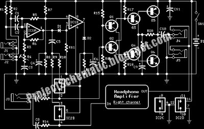
An audio power amplifier circuit for a 3-watt stereo amplifier using the MAX 7910 IC is explained below. The audio power amplifier circuit utilizing the MAX 7910 IC is designed to deliver a maximum output power of 3 watts per...
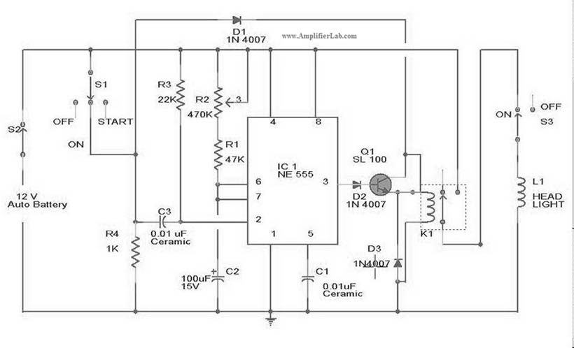
The circuit diagram for the automatic headlights turn-off circuit is presented here. This circuit can be installed in a car. The automatic headlights turn-off circuit is designed to enhance vehicle safety and convenience by ensuring that the headlights are automatically...
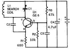
This metal detector circuit needs to be powered using a 9 volts power supply (DC) or a 9 volts battery. The C1 capacitor is a variable capacitor with a value of 365 pF, C2 is a 100 pF silver...
This is a complete circuit designed for an intercom system, which is illustrated in the accompanying diagram. The circuit utilizes a microphone amplifier based on IC1A, featuring two integrated circuits: the LM358, a low-power dual operational amplifier, and either...
This innovative buzzer circuit incorporates a relay connected in series with a small audio transformer and a speaker. When the switch is activated, the relay is energized through the primary winding of the transformer and the closed relay contact....
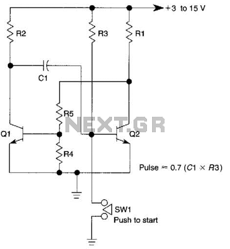
This circuit is activated when switch SW1 is pressed, grounding the base of transistor Q2. The pulse rate is approximately equal to 0.7 multiplied by the product of resistor R3 and capacitor C1. The described circuit features a transistor Q2,...