
Honda CB750 Electrical

The Honda CB750 electrical circuit diagram is designed to facilitate the understanding and troubleshooting of the motorcycle's electrical system. This circuit encompasses several critical components that contribute to the overall functionality of the vehicle.
The turn signal relay is an essential part of the signaling system, allowing for the activation and deactivation of the turn signals when the rider engages the corresponding switch. This relay ensures that the turn signals operate in a timed sequence, providing clear indications to other road users.
The oil pressure switch is a safety feature that monitors the engine's oil pressure. If the oil pressure drops below a certain threshold, the switch activates a warning light on the dashboard, alerting the rider to potential issues that could lead to engine damage. This component is vital for maintaining engine health and longevity.
The neutral switch serves to indicate when the motorcycle is in neutral gear. This switch is crucial for starting the engine, as it prevents the engine from being started while in gear, thereby enhancing rider safety. When the transmission is in neutral, the switch closes the circuit, allowing the starter motor to engage.
In addition to these components, the circuit also includes various fuses, connectors, and wiring harnesses that interconnect the electrical system, ensuring reliable operation of all electrical functions. The schematic provides a visual representation of these connections, which is invaluable for maintenance and repair tasks. Understanding this electrical circuit diagram is essential for technicians and enthusiasts alike, enabling effective troubleshooting and modifications to the Honda CB750's electrical system.The following circuit shows about Honda CB750 Electrical Circuit Diagram. Features: turn signal relay, oil pressure switch, neutral switch, .. 🔗 External reference
Related Circuits
A 2005 McGregor 26 sailboat is equipped with a Standard Horizon CP150C GPS unit. After relocating the boat to British Columbia, Canada, the GPS unit failed to power on, despite being brand new and unused by the original owner....
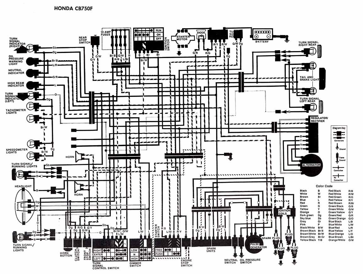
The following account presents the electrical wiring diagram for the Honda Motorcycle CB750F. It illustrates the connections between various Honda components, including the right turn signal indicator light, oil pressure warning light, neutral indicator, high beam indicator, turn signal...
1988 Honda Civic Tail Light Wiring Diagram. The 1988 Honda Civic tail light wiring diagram provides a detailed representation of the electrical connections and components associated with the tail light system of the vehicle. This schematic typically includes information on...
The Brushless DC motor with permanent magnetism is an advanced electrical machine characterized by innovative principles and technology. It consists of three main components: the Brushless DC motor body (BLDCM), a trochanter position transducer (RPS), and a control unit...
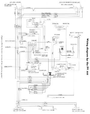
The following circuit illustrates the wiring diagram for the Volvo PV444, a vintage car electrical circuit. It provides an electrical understanding of this uni-body vehicle. The Volvo PV444 wiring diagram serves as a crucial reference for understanding the electrical system...
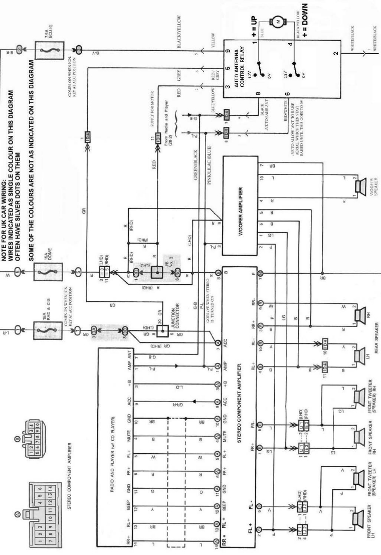
The following circuit illustrates an electrical circuit diagram for the MR2 MKII electric aerial. Features include control by an Aerial Control Relay, which consists of... The MR2 MKII electric aerial circuit is designed to facilitate the automatic operation of the...