
Wiring Diagram And Electrical Circuit For Volvo PV444

The Volvo PV444 wiring diagram serves as a crucial reference for understanding the electrical system of this classic automobile. This vintage car features a uni-body construction, which integrates the body and chassis into a single component, enhancing structural integrity and reducing weight.
The wiring diagram typically includes various components such as the ignition system, lighting, battery connections, and the alternator. Each component is represented with clear symbols and connections, allowing for easy identification and troubleshooting.
The ignition system in the PV444 consists of the ignition coil, distributor, and spark plugs. The wiring diagram outlines the connections between these components, ensuring proper voltage supply and timing for optimal engine performance.
The lighting system includes front and rear headlights, turn signals, and interior lights. The diagram specifies the wiring paths and the fuse protection for each circuit, which is essential for maintaining safety and functionality.
Furthermore, the battery connections are depicted, showing how the battery connects to the starter motor and the electrical system. The alternator's role in charging the battery while the engine is running is also highlighted, ensuring the vehicle remains operational.
Understanding this wiring diagram is vital for restoration projects or routine maintenance of the Volvo PV444, as it provides essential insights into the electrical layout and helps in diagnosing issues that may arise over time.The following circuit shows about Volvo PV444 Wiring Diagram Vintage Car Electrical Circuit. Features:electrical understanding of this uni-body .. 🔗 External reference
Related Circuits
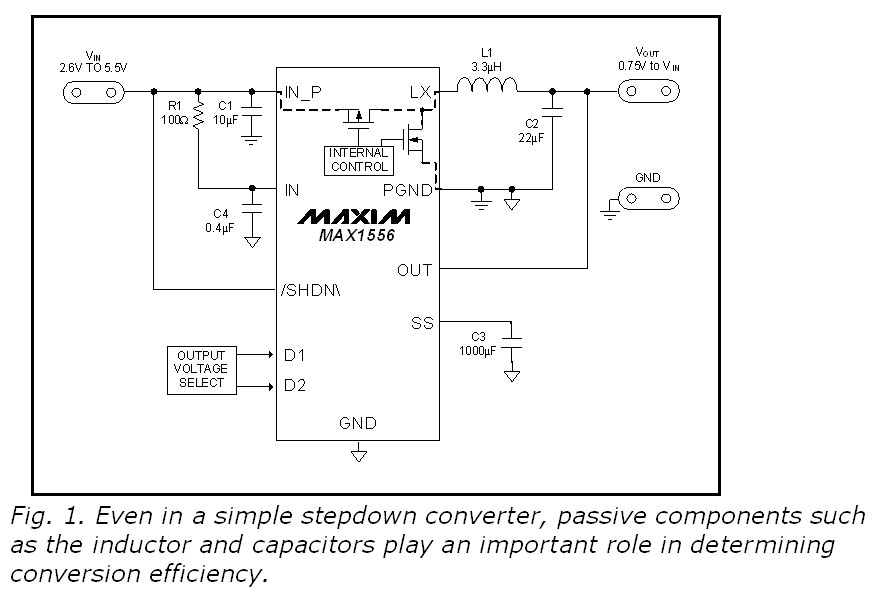
This blog provides insights into SMPS (Switched-Mode Power Supply) circuit diagrams. It offers valuable information for those interested in understanding this topic. Switched-Mode Power Supplies (SMPS) are crucial in modern electronic devices due to their efficiency and compact design. An...
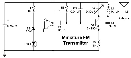
To replace a microphone with a 3.5" audio jack in a circuit, modifications will be necessary. The circuit currently utilizes an electret microphone, and adjustments must be made to accommodate the audio jack for audio transmission. The audio jack...
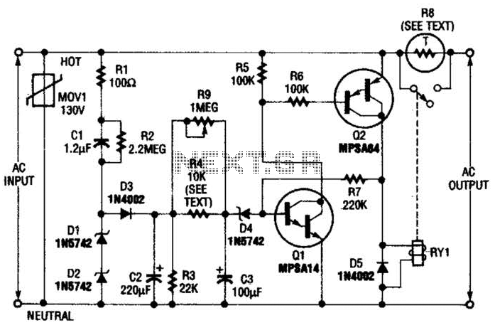
Q1 is an NPN Darlington transistor, and Q2 is a PNP Darlington transistor. MOV1 is a metal-oxide varistor, while R8 is a thermistor used for limiting inrush current. This circuit is designed to limit AC line current to a...
This UHF wideband amplifier (Ultra High Frequency amplifier) provides a total gain of 10 to 15 dB in the frequency range of 400 to 850 MHz, making it suitable for areas with weak TV signals. For optimal performance, the...
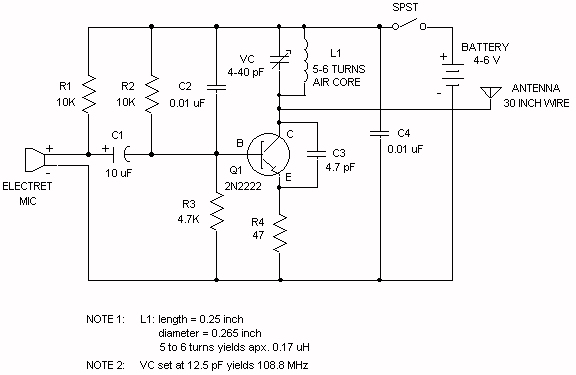
The electret microphone operates with a current of 200 µA, which varies by ±3 µA in response to sound waves. This variation results in a voltage of 2V across resistor R1 and 4V across the microphone. As sound waves...
This simple charger utilizes a single transistor as a constant current source. The voltage across the pair of 1N4148 diodes biases the base of the BD140 medium power transistor. The circuit operates by employing the BD140 transistor to regulate the charging...