Two-LED Pilot Light
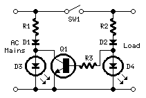
This circuit was designed on request and can be useful to those wishing to have, say, a red LED illuminated when an appliance is on and a green LED illuminated when the same appliance is off. Any mains operated appliance can be monitored by this circuit, provided a suitable mains switch, capable of withstanding the full load current, is used for SW1. When SW1 is closed, the load and D4 are energized, Q1 is saturated and shorts D3, thus preventing its illumination. Notes: * Change R1 and R2 to 15K 1W for 115Vac mains operation. * SW1 must be capable of withstanding the appliance's full load current and voltage.
The described circuit functions as a dual LED indicator for the operational status of a mains-operated appliance. It employs a simple relay or transistor switch mechanism to control the illumination of two LEDs based on the state of the connected appliance.
The circuit includes a switch (SW1) that is integrated into the mains supply line of the appliance. This switch must be rated for the full load current and voltage of the appliance to ensure safe operation. When the appliance is powered on, SW1 closes, allowing current to flow through the circuit.
The red LED (D4) is connected in parallel with the load; thus, when the appliance is on, the current energizes the load and D4. In this state, transistor Q1 is driven into saturation, effectively shorting the path to the green LED (D3), preventing it from lighting up. This provides a clear visual indication that the appliance is operational.
Conversely, when the appliance is turned off, SW1 opens, cutting off the current flow. This deactivates Q1, which in turn allows current to flow through D3, illuminating the green LED. This dual-color indication system provides immediate feedback on whether the appliance is on (red LED) or off (green LED).
For optimal performance, it is recommended to adjust the values of resistors R1 and R2 to 15K 1W for operation in a 115V AC mains environment. This adjustment ensures that the current flowing through the LEDs and the base of the transistor is within safe limits while providing adequate brightness for visual indication.
Overall, this circuit is a practical solution for monitoring the status of appliances, enhancing user awareness of operational states through simple yet effective LED indicators.This circuit was designed on request and can be useful to those whishing to have, say, a red LED illuminated when an appliance is on and a green LED illuminated when the same appliance is off. Any mains operated appliance can be monitored by this circuit, provided a suitable mains switch, capable of withstanding the full load current, is used for SW1.
When SW1 is closed, the load and D4 are energized, Q1 is saturated and shorts D3, thus preventing its illumination. Notes: * Change R1 and R2 to 15K 1W for 115Vac mains operation. * SW1 must be capable of withstanding the appliance`s full load current and voltage 🔗 External reference
