
Power Flip Flop Using A Triac

This circuit utilizes a power flip-flop configuration that leverages the unique properties of triacs, particularly their ability to conduct in both directions and their low cost, making them ideal for applications in model railways. The bistable nature of the flip-flop allows for stable operation, switching between states based on the activation of the reed switches by the permanent magnet on the model train. The incorporation of parallel reed switches (S3 and S4) ensures that the circuit can respond to the train's movement in both directions, enhancing its functionality.
The RC network, comprising capacitor C1 and resistor R2, plays a crucial role in phase shifting, which is essential for maintaining the trigger current necessary for the triac's operation. This design enables the triac to be triggered at the optimal moment when the load voltage approaches zero, ensuring reliable operation. The output load can be tailored to various applications, including lighting and solenoid devices, providing versatility in usage.
The use of an LED indicator across the output adds a visual element to the circuit, allowing for easy monitoring of the flip-flop's state. While the circuit is primarily designed for model railways, its principles can be applied to other electronic systems that require bistable operation. The option to replace reed switches with pushbutton switches further enhances the circuit's adaptability.
In terms of component specifications, the TIC206D triac is suitable for this application due to its current rating. However, considerations for heat dissipation must be taken into account if the load current exceeds recommended limits. Adjustments to the capacitor value can be made to ensure optimal performance, particularly if the triggering pulses are found to be inadequate. This flexibility in design and components makes the circuit a robust choice for various electronic applications.This approach can be demonstrated using the rather unusual semiconductor power flip-flop described here. A flip-flop is a toggling circuit with two stable switching states (bistable multivibrator). It maintains its output state even in the absence of an input pulse. Flip-flops can easily be implemented using triacs if no DC voltage is available. Triacs are also so inexpensive that they are often used by model railway builders as semiconductor power switches. The decisive advantage of triacs is that they are bi-directional, which means they can be triggered during both the positive and the negative half-cycle by applying an AC voltage to the gate electrode (G). The polarity of the trigger voltage is thus irrelevant. Triggering with a DC current is also possible. Figure 1 shows the circuit diagram of such a power flop-flop. A permanent magnet is fitted to the model train, and when it travels from left to right, the magnet switches the flip-flop on and off via reed switches S1 and S2.
In order for this to work in both directions of travel, another pair of reed switches (S3 and S4) is connected in parallel with S1 and S2. Briefly closing S1 or S3 triggers the triac. The RC network C1/R2, which acts as a phase shifter, maintains the trigger current. The current through R2, C1 and the gate electrode (G) reaches its maximum value when the voltage across the load passes through zero.
This causes the triac to be triggered anew for each half-cycle, even though no pulse is present at the gate. It remains triggered until S2 or S4 is closed, which causes it to return to the blocking state. The load can be incandescent lamps in the station area (platform lighting) or a solenoid-operated device, such as a crossing gate.
The LED connected across the output (with a rectifier diode) indicates the state of the flip-flop. The circuit shown here is designed for use in a model railway system, but there is no reason why it could not be used for other applications. The reed switches can also be replaced by normal pushbutton switches. For the commonly used TIC206D triac, which has a maximum current rating of 4 A, no heat sink is necessary in this application unless a load current exceeding 1 A must be supplied continuously or for an extended period of time.
If the switch-on or switch-off pulse proves to be inadequate, the value of electrolytic capacitor C1 must be increased slightly. 🔗 External reference
Related Circuits
The CLOCK input indicates that it is edge-triggered, responding to abrupt changes in voltage rather than gradual changes or steady logic levels. The CLOCK input of the 4013 D-type bistable is specifically rising-edge triggered, meaning it only reacts to...

A 0.1µF capacitor and a 500µF electrolytic capacitor were connected to both the transmitter and the receiver, but the system did not function as expected. Attempts to add diodes were also unsuccessful. Clarification is needed regarding the behavior of...
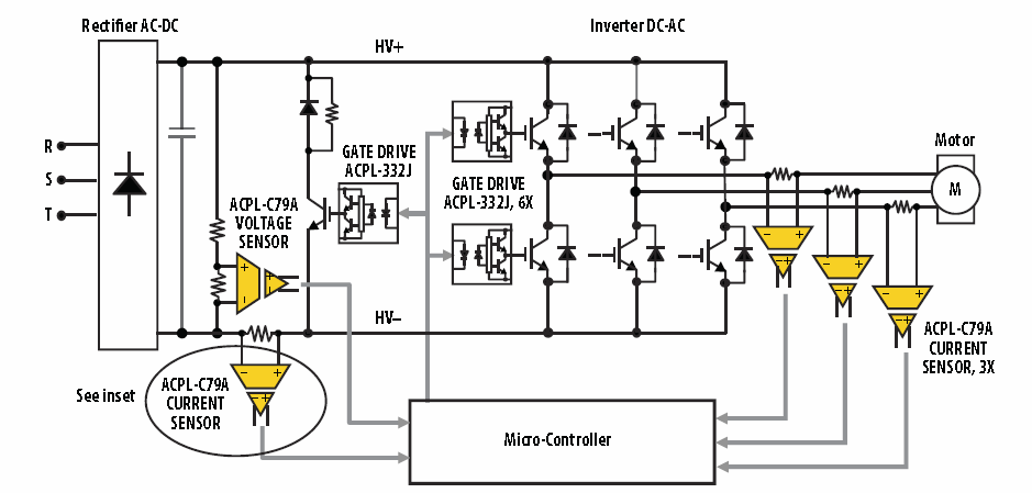
Insulated-gate bipolar transistors (IGBTs) require comprehensive protection to prevent damage and failures due to conditions such as short circuits, overloads, and overvoltages. This protection is essential for ensuring safe and stable operation of power converters in applications including motor...

This circuit illustrates a 32.768 kHz micro-power clock oscillator, suitable for use in mobile phones, laptop computers, and home appliances. It generates a clock signal that can be utilized in various applications. The 32.768 kHz micro-power clock oscillator circuit is...
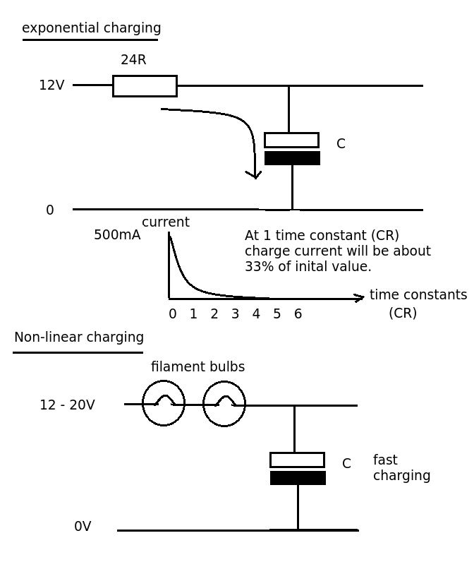
Designing a simple current limiter that charges a large 4.7mF capacitor with a charge current of approximately 500mA from a supply voltage of 10-20V. The dilemma is that there are existing MMBT2222A transistors available, which would be preferable to...
The fixed voltage power supply is useful in applications where an adjustable output is not required. This supply is simple, but very flexible as the voltage it outputs is dependent only on the regulator and transformer you choose. The...