
how to make vibration detectormeter

The vibration level detector circuit utilizes a piezoelectric transducer as the primary sensor element. When external vibrations occur, the transducer converts mechanical energy into electrical signals. These signals are proportional to the intensity of the vibrations and are processed by the LM3915 integrated circuit, which is designed for LED bar graph displays. The LM3915 can drive multiple LEDs and is configured to light up a number of LEDs corresponding to the amplitude of the input signal. This creates a visual representation of the vibration levels detected.
The circuit can be enhanced with additional features such as a threshold detection mechanism. This would allow the circuit to trigger an alarm or activate a relay if the vibration exceeds a predefined limit. Such modifications make the circuit suitable for applications in safety systems or monitoring environments where excessive vibrations may indicate potential hazards.
The power supply for this circuit is efficiently managed, with the LM3915 requiring minimal current. The use of a 9V PP3 battery not only allows for extended operation but also enhances the portability of the device, making it convenient for various applications, including field testing and monitoring in different environments.
Overall, the vibration level detector circuit represents a versatile and user-friendly solution for monitoring vibrations, with the potential for customization to meet specific user needs and applications.Whether it`s truckthrottling over the highway, or an airplane roaring about the sky, or whether it`s a knock on the door or a purring of the cat or simply your heartbeats, the vibration level detector circuit explained here will sense them all and convert into beautifulsequencingLED light bar graph indications. The number of LEDs lit in the bar graph at any particular instantindicatesthe magnitude of the vibration force at that particular instant. Vibration is nothing but the ruffling of the air due a corresponding force generated from an external medium. Forexamplewhen we speak, our vocal chords vibrate and generate the corresponding patterns of disturbance in the surrounding air.
When these air vibrations enter our ear, our eardrum also vibrate at the same frequency making it audible toour respectivesensory organs. The pitch of a vibration also becomes a major factor in determiningtheirnature and strength. Pitch and frequency are probably the two factors which make a particular vibrating information more distinct with their technical specs.
As an example, a whistling sound may be shrill and might reach longer distances, but the grumbling sound from a mixer grinder even being much stronger won`t reach across longer distances. Though our ear isequippedwith pretty impressive detecting capabilities, these organs cannot tell you the exact magnitude of a particular vibration force.
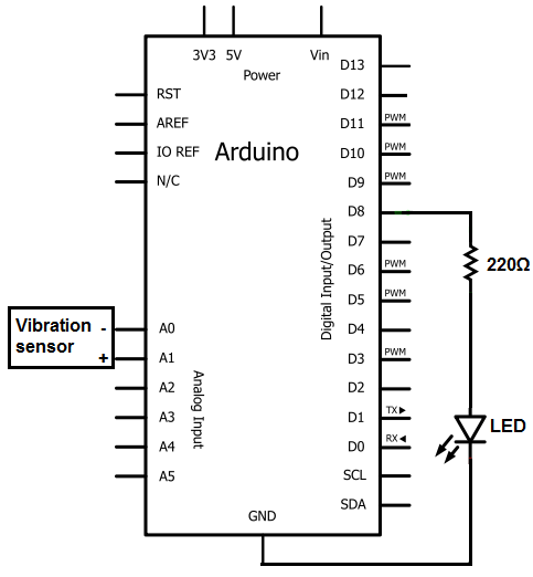
The circuit diagram below shows a rather simple configuration using the versatile IC LM3915 from TEXAS INSTRUMENTS, which aloneperformsthe function of sensing as well as displaying the vibration levels. Sound vibration force striking the piezo electric transducer generate tiny electrical pulses inside the transducer, or rather the device converts all vibrations hitting its surface into small electrical signals varying in amplitude whichcorrespondsto the strength of the strikingvibrations.
These tiny electrical pulses from the transducer is effectively amplified and processed inside the IC LM3915 and the relevant sequencing LEDdisplayisgeneratedacross the outputs of the IC. The LEDs connected at the outputs illuminate in randomly running patterns from the start point to theendpoint of thearray, displayingthe relevant information about the captured vibration signals.
This vibration detector or meter circuit can befurthermodified for more serious applications by including analarmstage or a relay driver stage for triggering them in case athreateninglevel of vibrating force isdetected. The application may be user specified and therefore the present circuit might be configured or optimized in numerous different ways.
The IC needs negligible current andthereforea 9V PP3 battery would providesufficientlife to sustain the circuit, almost forever and also this makes the unit very portable and can be installed at any desired crevice or location. The above circuit was successfully built by one of the keen readers of this blog, ADMIN. The following video was submitted by him which displays the practical working of his built prototype.
🔗 External reference
Related Circuits

Tape isolate single-phase power factor correction (PFC) that utilizes DC/DC converters, consisting of two cables. The three-phase PFC is formed by connecting three single-phase PFCs in parallel at the output. This configuration is based on a matrix-type DC/DC converter...

An article on how to create an inverter using a simple 40-watt inverter circuit diagram and schematics. This inverter converts 12 volts to 220 volts using the CD4047 integrated circuit. The described inverter circuit utilizes the CD4047 IC, which is...
The sensors consist of a thin strip of piezoelectric material with a rivet at one end acting as a weight. When vibration occurs, the weight moves, stressing the piezo material, which generates a spike in voltage that can reach...

This digital voltmeter is suitable for measuring the output voltage of a DC power supply. It features a 3.5-digit LED display with a negative voltage indicator, capable of measuring DC voltages from 0 to 199.9V with a resolution of...
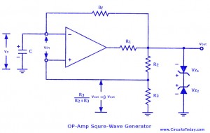
Non-sinusoidal waveform generators are also referred to as relaxation oscillators. The op-amp relaxation oscillator described is a square wave generator. Generally, square waves are relatively simple to produce. Similar to the UJT relaxation oscillator, the frequency of oscillation in...
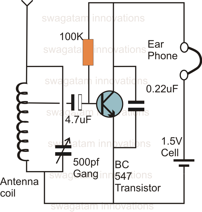
This is likely the simplest radio that can be assembled. The circuit design is straightforward enough to be completed in just a few minutes, allowing users to listen to their favorite programs immediately. The circuit of a single transistor...