
How to make an Astable or Free running Multi vibrator using 741 Op-Amp

The op-amp relaxation oscillator circuit features a straightforward configuration that can be implemented with minimal components. The primary elements include an operational amplifier, two Zener diodes for voltage limiting, a feedback resistor, and a capacitor. The operational amplifier is configured in an inverting mode, where the feedback loop incorporates the Zener diodes to stabilize the output voltage levels. The feedback resistor (R) and the capacitor (C) together establish the time constant for the charging and discharging cycles, influencing the frequency of the generated square wave.
The circuit's behavior can be analyzed through its transfer function, which reflects the relationship between the input and output voltages. The integration of the output voltage by the capacitor creates a phase shift that is crucial for the oscillatory behavior. The hysteresis introduced by the positive feedback ensures that the transitions between high and low states are sharp, minimizing the risk of oscillation instability.
Furthermore, the choice of Zener diodes impacts the output voltage levels and, consequently, the symmetry of the square wave. For applications requiring precise timing or frequency characteristics, careful selection of the resistor and capacitor values is essential. The circuit can also be adapted for various applications, such as clock generation, tone generation, or signal modulation, by adjusting component values or incorporating additional circuitry. Overall, the op-amp relaxation oscillator serves as a versatile building block in waveform generation, suitable for a wide range of electronic applications.The non-sinusoidal waveform generators are also called relaxation oscillators. The op-amp relaxation oscillator shown in figure is a square wave generator. In general, square waves are relatively easy to produce. Like the UJT relaxation oscillator, the circuit`s frequency of oscillation is dependent on the charge and discharge of a capacitor C thr ough feedback resistor R, . The heart of the oscillator is an inverting op-amp comparator The compa rator uses positive feedback that increases the gain of the amplifier. In a comparator circuit this offer two advantages. First, the high gain causes the op-amp`s output to switch very quickly from one state to an other and vice-versa.
Second, the use of positive feedback gives the circuit hysteresis. In the op-amp square-wave generator circuit given in figure, the output voltage vout is shunted to ground by two Zener diodes Z1 and Z2 connected back-to-back and is limited to either VZ 2 or VZ 1. A fraction of the output is fedback to the non-inverting (+) input terminal. Combination of IL and C acting as a low-pass R-C circuit is used to integrate the output voltage vout and the capacitor voltage vc is applied to the inverting input terminal in place of external signal.
The differential input voltage is given as vin = vc - ² vout When vin is positive, vout = Vz1 and when vin is negative vout = + Vz 2. Consider an instant of time when vin < 0. At this instant vout = + Vz 2, and the voltage at the non-inverting (+) input terminal is ² Vz 2, the capacitor C charges exponentially towards Vz 2, with a time constant Rf C.
The output voltage remains constant at Vz 2 until vc equal ² Vz 2. When it happens, comparator output reverses to Vz 1. Now vc changes exponentially towards-Vz1 with the same time constant and again the output makes a transition from -Vz1 to + Vz 2. when vc equals - ²Vz 1 The time period, T, of the output square wave is determined using the charging and discharging phenomena of the capacitor C.
The voltage across the capacitor, vc when it is charging from B Vz to + Vz is given by The frequency, f = 1/T, of the square-wave is independent of output voltage Vout. This circuit is also known as free-running or astable multivibrator because it has two quasi-stable states.
The output remains in one state for time T1 and then makes an abrupt transition to the second state and re mains in that state for time T2. The cycle repeats itself after time T = (T1 + T2) where T is the time period of the square-wave. The op-amp square-wave generator is useful in the frequency range of about 10 Hz -10 kHz. At higher frequencies, the op-amp`s slew rate limits the slope of the output square wave. The symmetryof the output waveform depends on the matching of two Zener diodes Z1 and Z2. The unsymmetrical square-wave (T1 not equal to t2) can be had by using different constants for charging the capacitor C to +Vout and -Vout
🔗 External reference
Related Circuits
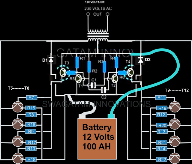
The current design of a power inverter offers an efficiency of approximately 85% and a power output exceeding 200 watts. This document provides a complete circuit schematic and detailed building procedure for a home-built power inverter. While numerous articles...
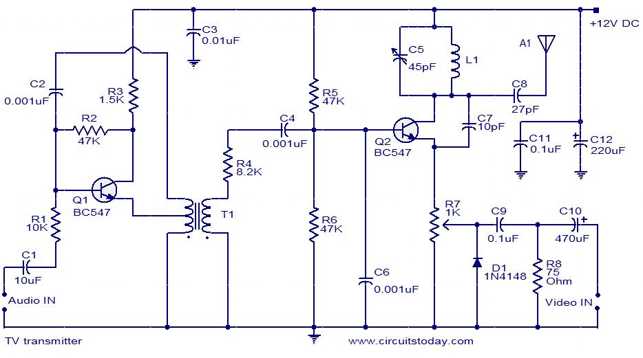
A simple two-transistor TV transmitter circuit that operates from 12V. It is compatible with PAL B and PAL G systems. The described circuit utilizes two transistors to create a basic television transmission system capable of operating on a 12V power...
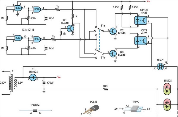
This circuit utilizes low-voltage AC to power a string of approximately 50 bi-color LEDs, with two LEDs connected in inverse parallel. The power supplied to the LEDs is managed by a Triac and two optocouplers, whose phototransistors are also...
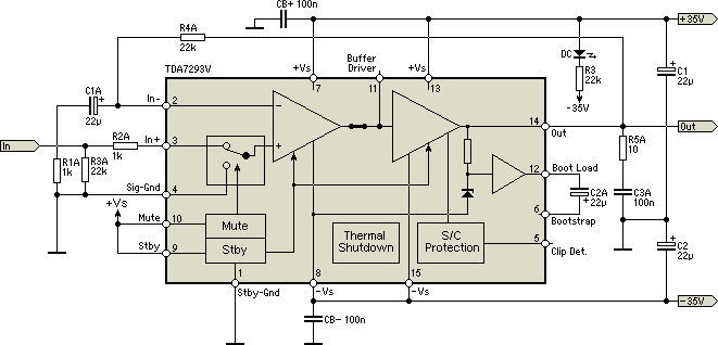
As readers may know, there are several power amplifier projects, including two that utilize integrated circuit (IC) power amplifiers, commonly referred to as power op-amps. Both of these projects have gained popularity, and this new project is not intended...
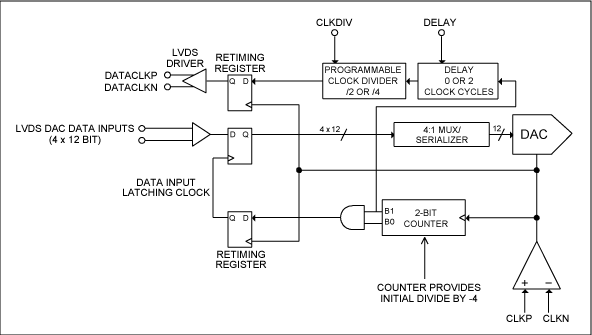
This application note provides insight into how to synchronize multiple high-speed DACs in transmitter applications. This document outlines the techniques and methodologies for synchronizing multiple high-speed Digital-to-Analog Converters (DACs) in various transmitter applications. Synchronization is crucial in systems where multiple...
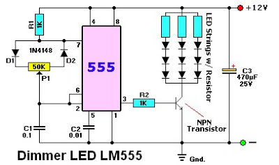
The LM555 timer IC can be utilized in various electronic projects, including the creation of an analog timer. According to the datasheet, the LM555 is versatile and can be adjusted to set timers based on specific requirements. The schematic...