
How to Measure Analog Distance Sensor

The software is provided on an "AS IS" basis without any warranties or representations, including implied warranties of merchantability or fitness for a particular purpose.
Switch Definitions:
- SWITCH1 (PORTM & 0x04) enables the bar graph.
- SWITCH2 (PORTM & 0x08) enables the seven-segment display.
- SWITCH3 (PORTM & 0x10) freezes the output on all displays.
- SWITCH4 (PORTM & 0x20) exits to the Forth prompt.
Forward Declaration:
- void DoBarGraph(int val);
- void LEDOutput(float cm);
- void BlankDigit(void);
- void DisplayBarGraph(int bar);
Multiple 10 Bit A/D Conversions with Results in a C Array:
A default sample size of 16 is defined, with a buffer to hold 10-bit A/D results. The function SampleToArray(int channel) uses 10-bit A/D on the specified channel (0-7) and places results in the one-dimensional C array c_results_10[]. The EXTENDED_ADDR union defined in TYPES.H converts the 16-bit array address into the 32-bit xaddr required by the ATDMultiple() function.
Initializations:
The InitAnalogPins(void) function zeros the standard C array to hold 10-bit results and activates the analog converters. The DigitArray holds 8-bit patterns used to light up the seven-segment display, with patterns written to each segment in a specified order.
The configuration indicates that A is the least significant bit and the decimal place is the most significant bit. LEDs are active low, meaning that a value of 0 indicates that the LED is lit, while a value of 1 indicates that it is dark. The DigitArray includes patterns for the digits 0-9 and a blank display.
This schematic and program facilitate the interaction with the Sharp GP2D12 IR sensor, allowing for real-time distance measurement and visual representation through LED displays, making it an effective tool for educational purposes and demonstrations in embedded systems and sensor integration.This video is a demonstration of reading an analog voltage, computing data, and controlling LEDs. I am using a Sharp GP2D12 Infrared (IR) sensor. More information about sharp distance sensors. The PDQ board connects to your host PC via a serial cable, running at a baud rate of 115200. The Mosiac IDE Plus compiles your C source code into a binary f ile. The Mosaic Terminal sends this file to the PDQ Board Users Guide. The QED-Forth RTOS on the PDQ Board Users Guide receives this file into ram, and then saves to flash memory after the download is complete. If you type "main" into the terminal followed by the `enter` key, the RTOS will execute main() from the loaded source code.
You also have the option to "Autostart" your program; this instructs the PDQ Board to execute main() at device power-on. The following schematic describes how all the components in this circuit are connected. Please download the pdf for a high resolution view of this document. #include
A 10 LED bar graph also fills up as the distance // decreases. 4 switches are connected to digital inputs which allow the user // to change the display. This program is meant to be a simple demonstration of // the onboard I/O available on the PDQ board. This program is a modified // version of the demo project entitled "Analog I/O Demo" which is provided with the // Mosaic IDE Plus. // Copyright 2010 Mosaic Industries, Inc. All Rights Reserved. // Disclaimer: THIS SOFTWARE IS PROVIDED ON AN "AS IS" BASIS, WITHOUT ANY // WARRANTIES OR REPRESENTATIONS EXPRESS OR IMPLIED, INCLUDING, BUT NOT // LIMITED TO, ANY IMPLIED WARRANTIES OF MERCHANTABILITY OR FITNESS // FOR A PARTICULAR PURPOSE.
// * Switch Definitions * // This #define masks one bit from Port M // if SWITCH1 is non-zero, then it is ON #define SWITCH1 ( PORTM & 0x04 ) // ON = enable bar graph #define SWITCH2 ( PORTM & 0x08 ) // ON = enable seven-segment display #define SWITCH3 ( PORTM & 0x10 ) // ON = freeze output on all displays #define SWITCH4 ( PORTM & 0x20 ) // ON = exit to forth prompt // * Forward Declaration * _Q void DoBarGraph( int val ); _Q void LEDOutput( float cm ); _Q void BlankDigit( void ); _Q void DisplayBarGraph( int bar ); // * Multiple 10 Bit A/D Conversions with Results in a C Array * #define DEFAULT_NUMSAMPLES 16 _qv uint c_results_10[DEFAULT_NUMSAMPLES]; // declare c buffer for 10 bit A/D results _Q void SampleToArray(int channel) // converts using 10bit A/D on specified channel (0-7), puts results in // the 1-dimensional C array c_results_10[] // We use the EXTENDED_ADDR union defined in TYPES. H to convert // the simple 16bit array address into the 32bit xaddr required by ATDMultiple() { xaddr xcbuffer = TO_XADDR(c_results_10, 0); //USAGE: ATDMultiple ( xaddr buffer, uint utime, int one_byte, // int numsequences, int starting_channel_id, int numchannels ); ATDMultiple(xcbuffer, 0xfff, 0, DEFAULT_NUMSAMPLES, channel, 1); } // * Initializations * _Q void InitAnalogPins(void) // zeros the standard C array to hold 10bit results; // turns on the analog converters { int i; ATDOn(0); // turn on converter for AN0-AN7 for(i=0;i
The pattern is written to each segment (denoted with letters) // in the following order, with an X for the decimal place: // XGFEDCBA // In this configuration, A is the least significant bit, and the decimal place // is the most significant bit. Remember that these LEDs are active low, so // 0 means lit, 1 means dark. // // 0 1 2 3 4 5 6 7 8 9 A Blank const char DigitArray[12] = { 0xc0, 0xf9, 0xa4, 0xb0, 0x99, 0x92, 0x
🔗 External reference
Related Circuits
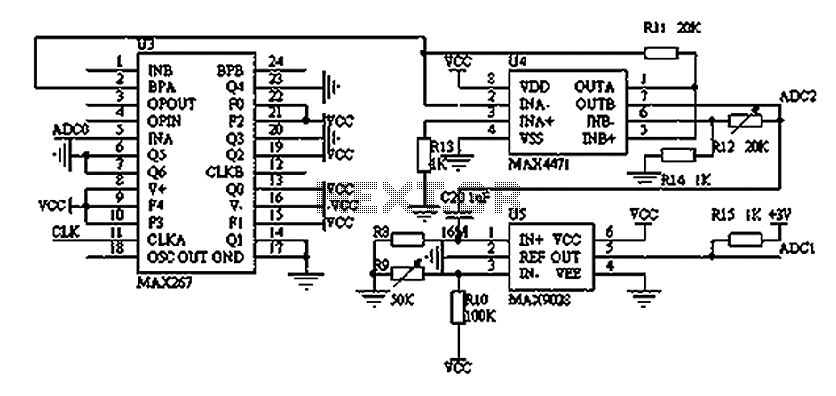
The filtering and amplifying circuit consists of two main components. The MAXIM MAX267 filter is an integrated circuit that can function as a low-pass, band-pass, high-pass filter, and other configurations, offering superior performance compared to traditional op-amp filters. The...
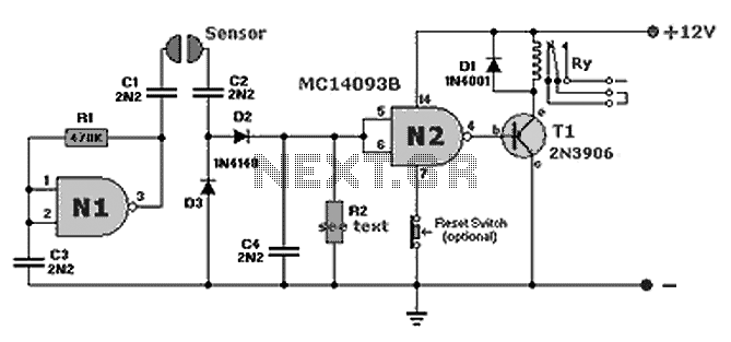
A compact fluid (water) sensor circuit that activates a relay for various applications. Additionally, a printed circuit board (PCB) is not necessary due to the small size of the circuit. The fluid sensor circuit is designed to detect the presence...

The robot requires a method for detecting obstacles (or other robots) without making physical contact. This capability allows the robot to determine whether to avoid or confront and investigate the obstacle based on its programming. This document outlines the...
R1 = 470K, N1, N2 = MC14093B, R2 = 15M, T1 = 2N3906 (also compatible: PN200, 2N4413), C1-C4 = 2.2nF (NTE159, ECG159, BC557, BC157, TUP), D1 = 1N4001, Ry = Relay (12V or matching supply voltage), D2, D3 =...
This circuit explains alternate wireless switching using an ultrasonic sensor. The distance of the switching range should be more than 10 meters. The described circuit employs an ultrasonic sensor to facilitate wireless switching, allowing for the activation or deactivation of...
A milliamp meter can be utilized as a voltmeter by incorporating a series resistance. The required resistance is calculated by dividing the full-scale voltage reading by the full-scale current of the meter movement. For example, using a 1 milliamp...