
ht gps audio revised schematic

The circuit design incorporates a MAX4467 voice amplifier, which is known for its low noise and high gain characteristics, making it suitable for amplifying audio signals from electret microphones. The inclusion of an attenuator at the output plays a critical role in managing the gain, especially when interfacing with microphones that may have varying output levels. The attenuator effectively reduces the gain from Av=5 to a level closer to unity, allowing for flexibility in signal handling without distortion or clipping.
The stability of the Vcc/2 supply is essential for the proper functioning of the MAX4467. The replacement of the original 1 µF capacitor with a 33 µF capacitor enhances the power supply's ability to maintain a stable voltage level, thereby preventing oscillations that could otherwise arise from the dynamic changes introduced by the attenuator. Oscillation can lead to unpredictable behavior in audio applications, making this modification crucial for reliable performance.
In addressing the switching mechanism, the design transitioned from a MOSFET relay to an optocoupler configuration. The optocoupler's CTR of about 100% ensures sufficient current transfer to activate the 2N2907 PNP transistor reliably. This change was motivated by the need for consistent performance, particularly given the temperature sensitivity observed in the MOSFET relay. The choice of using either a TO-92 or SOT-3 package for the 2N2907 transistors offers versatility in component selection based on the specific requirements of the application, including power dissipation constraints.
Overall, this circuit design exemplifies a thoughtful approach to managing gain and ensuring stability in audio amplification, with provisions for component selection that accommodate various operational scenarios. Future adjustments may be considered if the performance with high-output microphone capsules proves to be inadequate, ensuring that the design remains adaptable to evolving needs.An attenuator on the output of the MAX4467 voice amp allows gains below unity. Right now, the MAX4467 has Av=5 and the attenuator cuts it back by about 1/5, so the overall gain is about unity. I have a bunch of surplus electret mic capsules and some have come through really hot; this allows backing the gain way down with the mic amp set to Av=1.
T hat requires stiffening the Vcc/2 supply by swapping in a 33 µF cap for the original 1 µF unit. If you don`t do that, the amp turns into a oscillator: the attenuator jerks the Vcc/2 supply around, which feeds back to the non-inverting input of the MAX4467. In principle, the gain should be less than unity, but I wouldn`t bet on it. The MOSFET relay sometimes didn`t quite turn on from the piddly 4 mA available through the ICOM IC-Z1A`s mic power supply; it was vaguely temperature dependent.
I returned to an ordinary optocoupler with a CTR of about 100% driving a 2N2907 PNP transistor, as in the first-pass design that you never saw. The two 2N2907 devices allow either a through-hole TO-92 or SMD SOT-3 package, depending on what you have and the power dissipation you need.
In my situation, the SMD version suffices, with less than 100 mV of VCE saturation. [Update: I`m not convinced the Vcc/2 supply is stiff enough. I ripped out the attenuator and cut the amp gain to 1. 0. If I get some really hot capsules, I`ll think it over a bit more. ] 🔗 External reference
Related Circuits

This is a CMOS-compatible (and ideally also TTL-compatible) input that includes over-voltage and under-voltage protection. Schmitt triggers are utilized to accommodate inputs with long transition times. It has been verified to function at frequencies up to 30 MHz. The described...
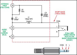
This document presents a concept for a low-cost adapter that enables the connection of a portable FM radio or MP3 player with an FM tuner to an external antenna and audio equipment, such as a hi-fi system or PC...
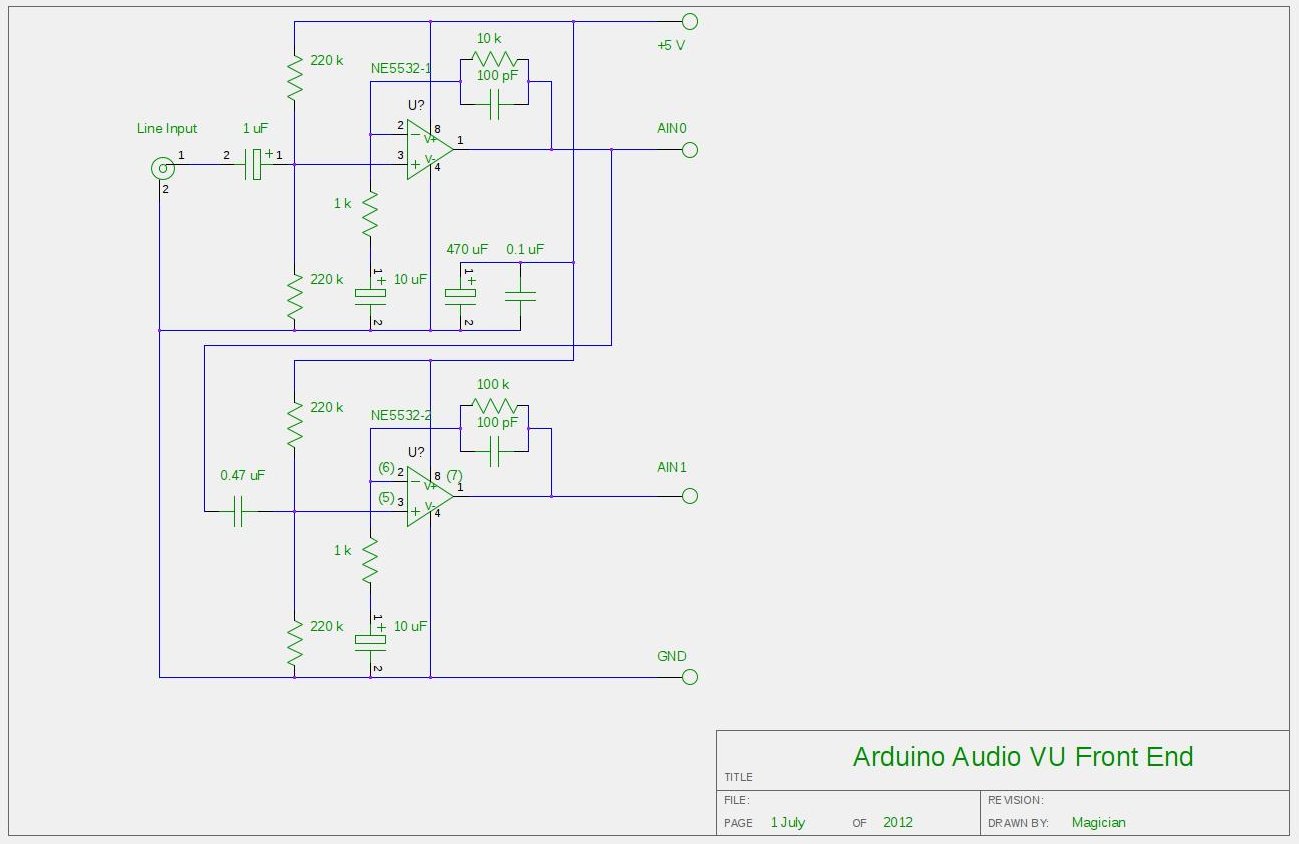
After experimenting with a stereo version of the VU meter described in a previous blog post, a studio-grade VU meter is now being presented. This meter features 24 steps, spaced equally every 3 dB, and covers a wide dynamic...
A 1969 Princeton Reverb amplifier is identified as utilizing the AA764 circuit design. Various online resources provide schematics for Fender amplifiers. The Princeton Reverb amplifier, particularly the model from 1969, is renowned for its warm tone and versatile sound characteristics,...
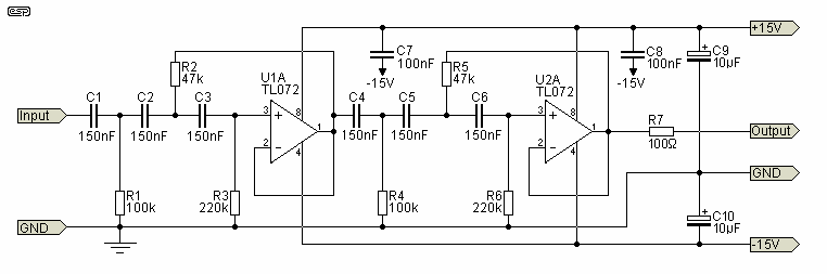
The circuit shown is completely conventional. The Q of the filters has been optimized to allow a higher input impedance than would otherwise be possible, with the final Q of the two filters being almost exactly 0.707 (i.e., a...
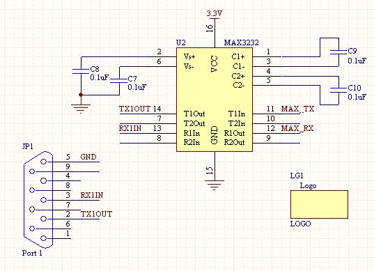
Once the setup of an RS232 connection is understood, it becomes a straightforward process for future projects. This design features a compact SMD version of the power supply, which can also be constructed using through-hole components on a breadboard....