
Humidity Sensor

Humidity measurement is critical in various applications, including meteorology, HVAC systems, agriculture, and food storage. The measurement is typically expressed in relative humidity (RH), which is the ratio of the current amount of water vapor in the air to the maximum amount of water vapor the air can hold at that specific temperature.
To create an electronic humidity sensor circuit, a common approach involves using a capacitive or resistive humidity sensor. Capacitive sensors operate by measuring changes in capacitance caused by the absorption of moisture in a hygroscopic material. In contrast, resistive sensors measure changes in resistance as humidity levels fluctuate.
A basic schematic for a capacitive humidity sensor circuit may include the following components:
1. **Humidity Sensor**: A capacitive sensor that changes its capacitance based on the surrounding humidity levels.
2. **Microcontroller**: A microcontroller such as an Arduino or PIC that reads the sensor output and processes the data.
3. **Analog-to-Digital Converter (ADC)**: If the microcontroller does not have a built-in ADC, an external ADC may be required to convert the analog signal from the humidity sensor into a digital signal for processing.
4. **Power Supply**: A stable power supply circuit to ensure the sensor and microcontroller operate within their specified voltage ranges.
5. **Display Module**: An optional LCD or LED display to visually present the humidity readings.
The circuit can be designed to include a feedback mechanism to adjust environmental conditions based on the measured humidity, such as activating dehumidifiers or humidifiers. Proper calibration of the sensor is essential for accurate readings, and regular maintenance may be necessary to ensure long-term reliability.
Overall, the design of a humidity measurement circuit requires careful consideration of the sensor type, the processing unit, and the interface for data output, ensuring that it meets the specific needs of the intended application.Introduction Humidity is the amount of water vapor in the air, expressed as a percentage of the maximum amount that the air could hold at the given temperature.. 🔗 External reference
Related Circuits
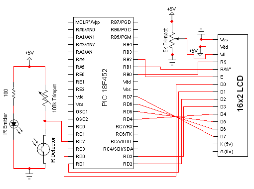
The circuit for the Digital Tachometer/RPM Counter consists of only a few devices. Wire them up according to the following circuit diagram. The PIC used is on a demonstration board, which means the clock, power, and ground pins are...
A touch sensor relaxation oscillator is utilized in the hysteresis lab. In this schematic, the variable capacitor is represented by a person's finger and a touch plate made from aluminum foil and packing tape. Code was developed for the...
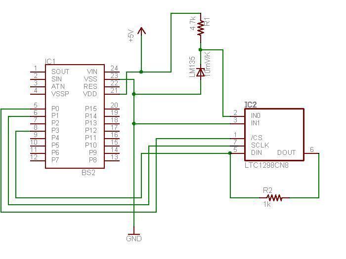
The schematic diagram illustrates the temperature sensor that is set to be launched. The LM135 sensor, functioning as a Zener diode, is connected via a foot-long cord to the circuit through a plug. This design allows the sensor to...
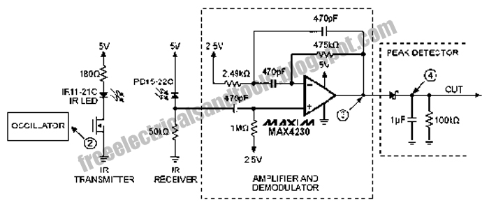
The following circuit illustrates an Infrared Proximity Sensor Circuit Diagram. This circuit is based on the MAX4230 integrated circuit. Features include a 10 kHz oscillator. The Infrared Proximity Sensor Circuit utilizing the MAX4230 integrated circuit is designed to detect the...

Numerous LED projects to ignite creativity. Light Emitting Diodes are easy to use and enhance the appearance of DIY electronic projects. LEDs (Light Emitting Diodes) are semiconductor devices that emit light when an electric current passes through them. They are...
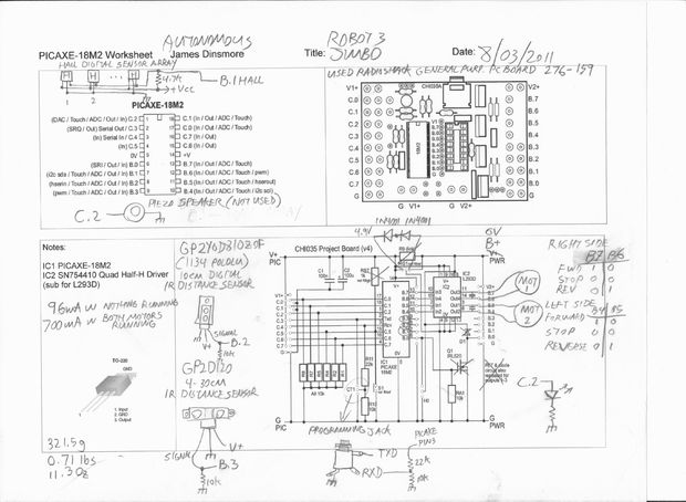
This is an autonomous robot designed to explore the interfacing of various sensors with a PICAXE processor. Its mission is to search for a magnet. The autonomous robot operates based on a microcontroller architecture centered around the PICAXE processor, which...