
humidity sensor circuit

This circuit is designed to accurately measure humidity levels by utilizing the characteristics of the LTC1043 integrated circuits, which are precision analog switches. The LTC1043A performs the function of inverting the reference voltage supplied by the LT1009, ensuring that the humidity sensor operates under a controlled negative voltage. This is crucial for maintaining sensor integrity and preventing electrochemical degradation over time.
The humidity sensor's capacitance is sensitive to changes in relative humidity, allowing for precise readings. The nominal capacitance of 400 pF at 76% RH means that as the humidity increases or decreases, the capacitance will change accordingly, following the slope of 1.7 pF/% RH. This relationship allows the circuit to convert changes in capacitance into measurable voltage changes.
The LTC1043B plays a vital role in the charge-pump operation by alternating between charging and discharging the humidity sensor. The use of pins 12B, 13B, and 14B facilitates the management of the sensor's charge state, ensuring that it is adequately charged to the negative potential established by the LTC1043A. The 1 µF capacitor acts as a coupling element, enabling effective charge transfer to the sensor while maintaining the necessary voltage conditions.
Overall, this circuit design exemplifies a robust approach to humidity sensing, leveraging precision components to ensure accurate and reliable performance.This circuit combines two LTC1043s with a based humidity transducer in a simple charge-pump based circuit. The sensor specified has a nominal 400 pF capacitance at RH = 76%, with a slope of 1.7 pF/% RH. The average voltage across this device must be zero. This provision prevents deleterious electrochemical migration in the sensor. The LTC1043A inverts a resistively scaled portion of the LT1009 reference, generating a negative potential at pin 14A.
The LTC1043B alternately charges and discharges the humidity sensor via pins 12B, 13B, and 14B. With 14B and 12 connected, the sensor charges via the 1 ^F unit to the negative potential at pin 14A.
Related Circuits
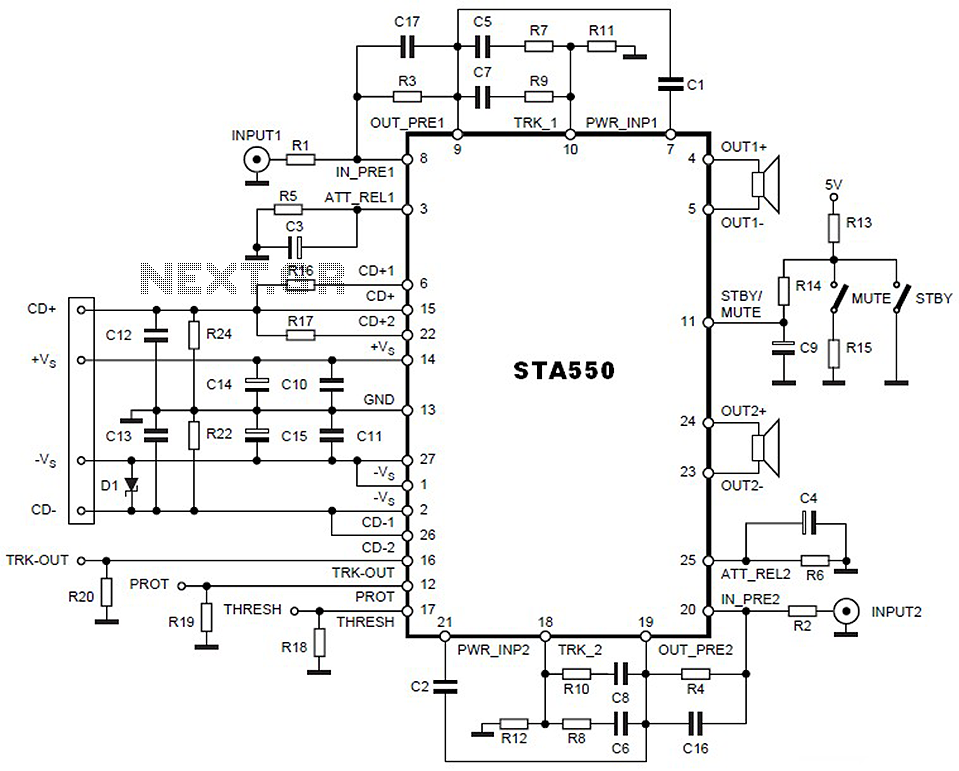
This is a 2 x 70W audio power amplifier circuit built using a single IC STA550. The amplifier circuit requires a few external components, primarily resistors and capacitors, and is straightforward to design. The STA550 audio amplifier can provide...
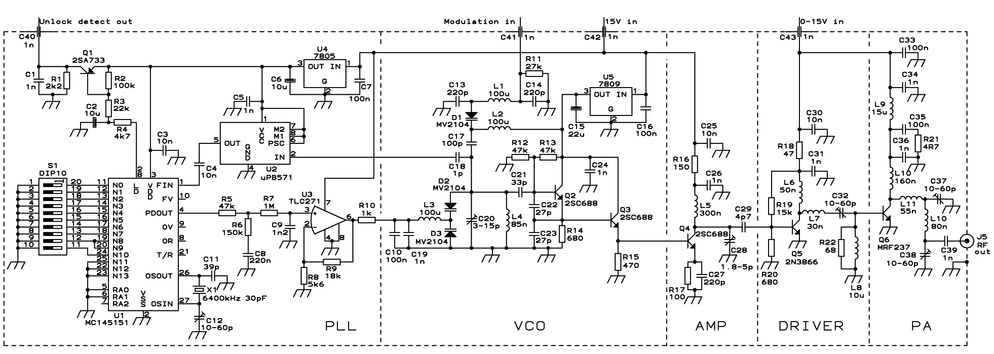
The PLL transmitter exciter is designed to provide a stable, low noise, frequency-selectable RF signal, which is amplified to a controllable output power sufficient to drive a power amplifier. It utilizes a PLL frequency synthesizer based on the MC145151,...
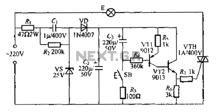
Another method employs a Zhu gall thyristor delay lamp circuit. Typically, a 220V AC supply is used, consisting of a step-down voltage half-wave rectifier circuit. The circuit outputs approximately 25V across the left and right terminals. At this point,...

The following circuit illustrates a Bedside Lamp Timer Circuit Diagram. This circuit is based on the CD4060 integrated circuit. Features: An LED illuminates for approximately 25 seconds. The Bedside Lamp Timer Circuit utilizes the CD4060 IC, which is a versatile...
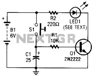
Used as a 10-second momentary illuminator, this circuit can be useful in other applications as well. Pressing SI charges CI, which holds Q1 on and keeps the LED lit for about 10 seconds. The circuit described functions as a momentary...
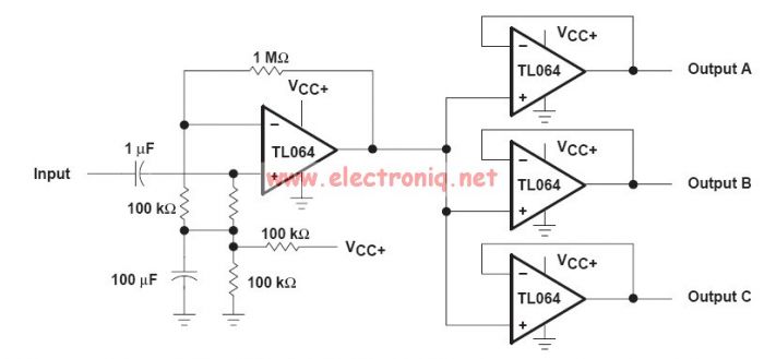
This audio distribution electronic project circuit diagram is designed using the TL064 or TL06 operational amplifiers and some other common electronic parts. The audio distribution circuit utilizes TL064 or TL06 operational amplifiers, which are quad op-amps known for their low...