
Hybrid mixer

In this circuit description, ICla and IClb refer to the inputs of a digital logic gate configuration where the 4011A integrated circuit (IC1) serves as a quad two-input NAND gate. Resistors R3 and R4 play a crucial role in biasing these inputs into their linear operating regions, ensuring that the gates function effectively without entering saturation or cutoff states. The proper biasing is essential for maintaining linearity, which is vital for the subsequent processing of signals.
The outputs from the gates are then fed into operational amplifier IC2. This op-amp is configured to combine the outputs from the digital gates, and its design is optimized for low output impedance. The low impedance output is critical for driving subsequent stages of the circuit, allowing for better signal integrity and reducing the impact of load variations on the output voltage levels.
The configuration of the circuit should ensure that the feedback and gain settings of the operational amplifier are appropriately adjusted to meet the required performance specifications. This might involve selecting suitable resistor values for the feedback network, depending on the desired gain and bandwidth characteristics of the op-amp stage. The overall design should also consider power supply requirements for both the digital and analog sections to ensure stable operation. Proper grounding and decoupling techniques are also recommended to minimize noise and interference within the circuit.ICla and b are biased into the linear regions by R3 and R4. (ICI must be 4011A) Outputs from gates are combined by op amp IC2, which provides low impedance output.
Related Circuits
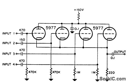
This circuit is utilized for combining four distinct positive-polarity marker pulses in a radar system. The reference for this information is the "Handbook Preferred Circuits Navy Aeronautical Electronic Equipment," Volume 1, Electron Tube Circuits, published in 1963, page N4-1. The...
Utilizes two distinct common-cathode video mixers. Identical heading markers are inserted into the front input 2 of both mixers, while the other inputs manage independent markers. The circuit employs two common-cathode video mixers, which are integral components for combining multiple...
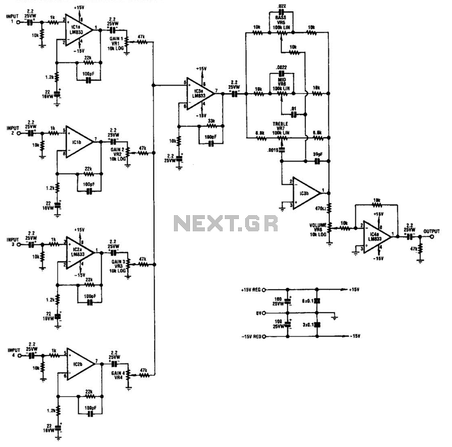
IC1-a, IC1-b, IC2-a, and IC2-b all operate with a gain of approximately 19. Their outputs are combined through level-control potentiometers, and the resulting signal is amplified by IC3-a before being sent to the tone-control stage IC3-b. Finally, the output...

The debate continues regarding whether valves or transistors are superior. This discussion will not be addressed here. However, if one cannot make their… The comparison between valves (vacuum tubes) and transistors has been a longstanding topic in the field of...
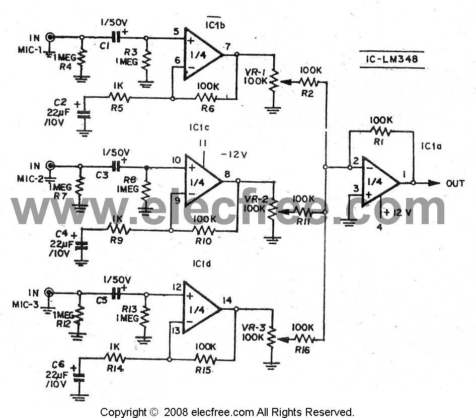
For those seeking a mixer with a microphone, this circuit is highly recommended for easy assembly. The proposed circuit is designed to serve as a microphone mixer, allowing users to blend audio signals from multiple microphones into a single output....
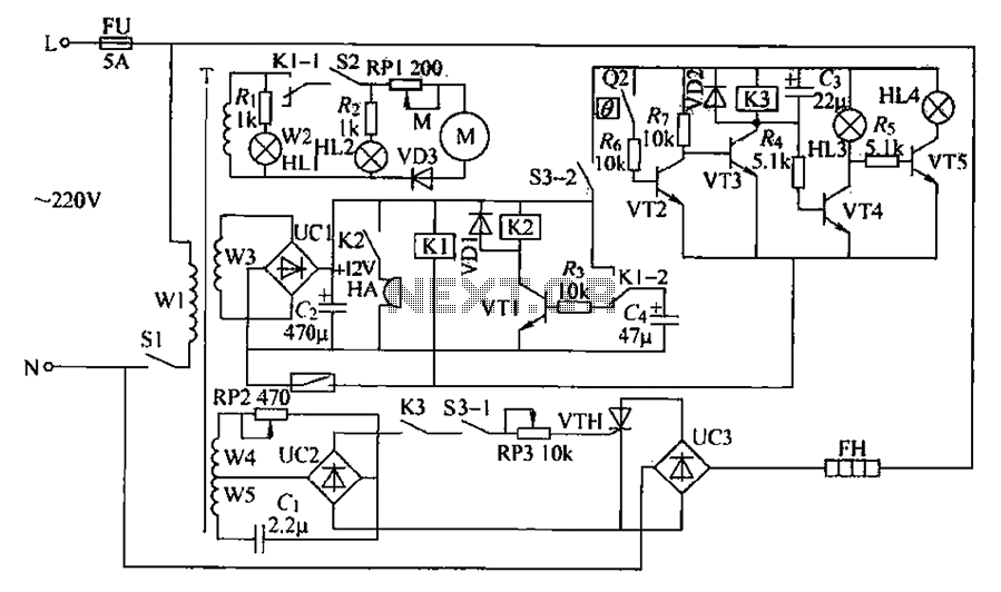
A chemical mixer circuit equipped with stirring speed control, a thermostat, and a timer alarm function is suitable for use in the chemical, steel, and other industries. The circuit includes components for heating, magnetic stirring, motor control, and timing...