
PWM Motor Speed Control Using Class D Audio Amplifier

The Class D audio amplifier circuit is designed to efficiently manage the speed of a PWM (Pulse Width Modulation) motor, making it particularly suitable for battery-operated portable devices. Class D amplifiers are known for their high efficiency, often exceeding 90%, which is crucial for extending battery life in portable applications.
In this circuit, the input audio signal is first processed and converted into a PWM signal. This conversion is achieved using a comparator that compares the input signal with a triangular waveform. The resulting PWM signal is then used to drive a power stage, typically consisting of MOSFETs or IGBTs, which switch on and off rapidly to control the power delivered to the motor.
The advantages of using a Class D amplifier for PWM motor control include reduced heat generation and improved battery efficiency. Since the switching elements operate in saturation and cutoff regions, power loss due to heat is minimized. This is particularly beneficial in applications where thermal management is critical.
Additionally, the circuit can incorporate feedback mechanisms to ensure precise control of motor speed and torque, enhancing the overall performance of the device. By adjusting the duty cycle of the PWM signal, the speed of the motor can be finely tuned, allowing for smooth operation across a range of speeds.
In summary, the Class D audio amplifier circuit for PWM motor speed control provides an effective solution for managing power in battery-powered devices, combining efficiency, performance, and the ability to maintain compact designs.This is class D audio amplifier circuit that is used to control PWM motor speed. This circuit has two advantages for battery-powered portable devices. First, . 🔗 External reference
Related Circuits
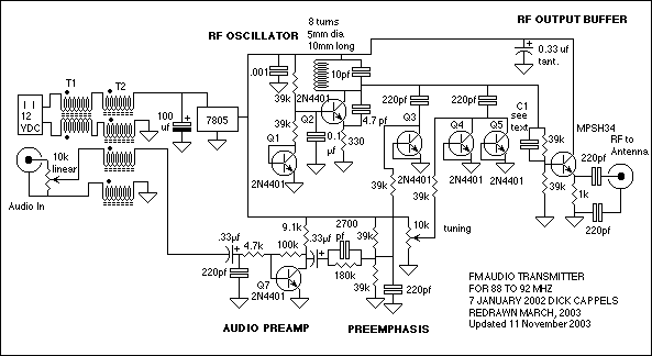
The circuit consists of a frequency modulated oscillator, an audio preamplifier with pre-emphasis to supply the frequency modulating signal, and a buffer amplifier to drive the antenna connector. Oscillator's frequency is determined by L1 resonating with the 10 pF...
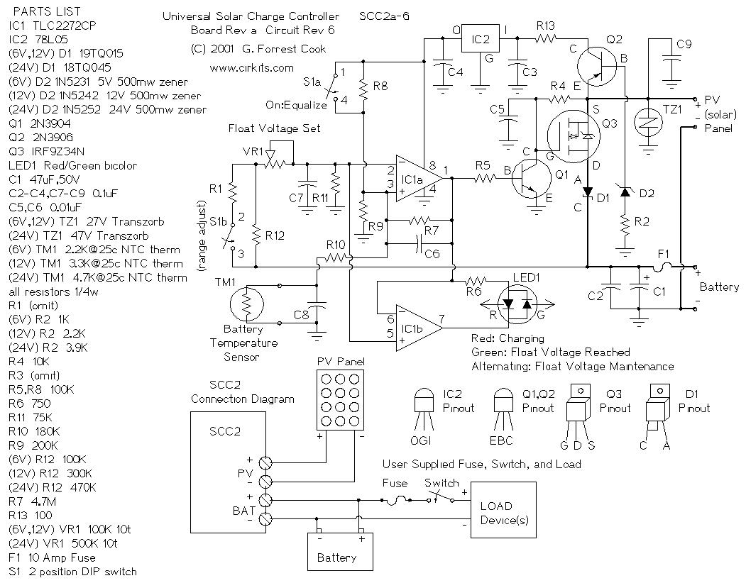
The SCC2 is a solar charge controller designed to manage the power transfer from a photovoltaic panel to a rechargeable battery. It includes a straightforward setup process utilizing a single potentiometer for adjusting the float voltage, an equalization function...
This car stereo booster utilizes an LM2896 integrated circuit, which features two amplifiers. It operates with supply voltages ranging from 3 to 15 volts. The power output is 2.5 watts per channel when connected to an 8-ohm load at...
The circuit's frequency oscillation is given by the formula f = 2.8 / [Cix(i1 + i2)]. By utilizing the specified values, the output frequency can be adjusted from 60 Hz to 20 kHz by rotating potentiometer R2. A portion...
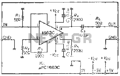
The PCI663 is a dynamic input, differential output type of integrated circuit (IC), but this circuit is designed with a single-ended output. The terminal resistance is set at 50 ohms, with a straight coupling configuration. The output voltage is...
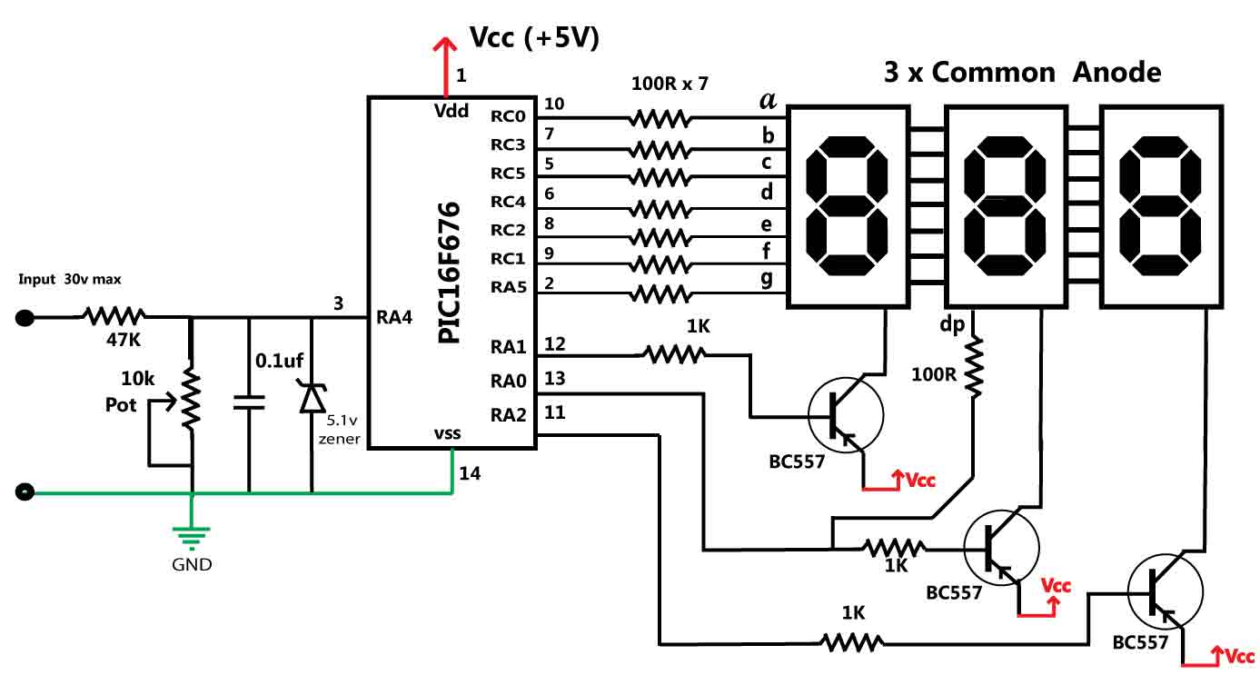
This is a simple application of the internal 10-bit ADC (analog-to-digital converter) of the PIC16F676 microcontroller. This circuit can be used to measure up to 30 V DC. Possible applications include a benchtop power supply or as a panel...