
IF AGO network circuit diagram

The described circuit utilizes the TL026C T1 voltage control amplifier, which is designed to provide gain control for intermediate frequency (IF) signals. This component is particularly advantageous in applications requiring automatic gain control (AGC) due to its ability to maintain a consistent output level across varying input signal amplitudes. The TL026C features low noise and high linearity, making it suitable for high-fidelity audio and RF applications.
In conjunction with the TL026C, the LT1014 quad op-amp can be employed to further process the signal. The LT1014 offers four independent, high-performance op-amps in a single package, allowing for versatile circuit configurations. Its characteristics include low offset voltage, low bias current, and high slew rate, contributing to overall system performance. This combination of components enables the design of a robust AGC circuit that can effectively handle a wide dynamic range of input signals while preserving signal integrity.
The overall schematic may include additional passive components such as resistors and capacitors to set the gain and filter the signal appropriately. By carefully selecting these components, the circuit designer can optimize the response time and stability of the AGC function, ensuring that it meets the specific requirements of the application. Proper layout and grounding techniques should also be employed to minimize noise and interference, enhancing the performance of the AGC system.A simple IF AGC signal over a wide dynamic range and excellent linearity characteristics, it may be composed of two chips to obtain: TL026C T1 voltage control amplifier IC and LT1014 (or any other similar basic quad op amp device ).
Related Circuits
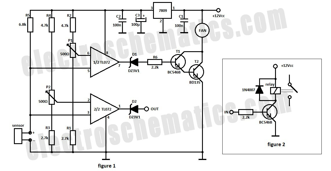
The automatic fan controller circuit depicted in the schematic features two comparators with distinct triggering points that can be adjusted independently. LM135 or... The automatic fan controller circuit is designed to regulate fan operation based on temperature variations. It employs...
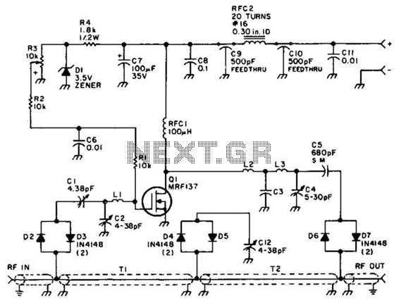
Using a power MOSFET, this amplifier can achieve a 2-W handheld radio power level, increasing it to approximately 10 W on the 2-meter band. A transmission-line RF switch is employed for transmit/receive (T/R) switching. The described amplifier utilizes a power...
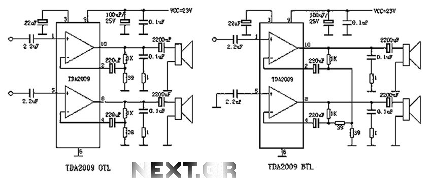
The audio circuit, commonly utilized in color television sets, features the TDA2009 integrated circuit. The pin configuration is as follows: Pin 1 is designated for the left channel input at 1.2V, Pin 2 serves as the left channel feedback...
The 555 timer on the right is configured as an alarm sound generator, while the second 555 timer on the left functions as a 1 Hz astable multivibrator. The output from the left timer modulates the frequency of the...
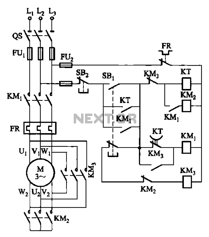
The circuit depicted in Figure 3-41 illustrates a Y-transfer process. When contact KMi is turned off, the motor undergoes a transition in the event of a power failure. Additionally, the main contact KM3 is disconnected when KM2 is activated,...
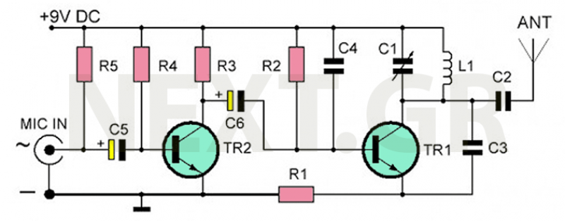
The recommended transmitter is straightforward to construct and suitable for beginners. Despite its simple design and compact size, it delivers remarkable performance. It operates for 12-15 hours on a 9-volt battery and has a transmission range of 100 to...