
Tape recorder position indicator-controller

To prevent the tape from becoming loose on the reel during rewind, a leader tape should be used. By resetting the counter at the starting point of the tape, a few feet from the end of the leader, the ZERO output can be activated to stop the recorder during rewind, ensuring that the leader remains on the reel. A 1-ohm resistor and a 0.0047 µF capacitor on the COUNT INPUT create a time constant of approximately 5 ms to debounce the reel switch. The Schmitt trigger on the COUNT INPUT of the ICM7217 conditions the signal before it is sent to the counter. This method can also be applied to debounce switch closure inputs in various other applications.
The circuit design employs an up/down counter configuration, specifically utilizing the ICM7217 integrated circuit, which is well-suited for precise counting applications. The LOAD REGISTER serves as a temporary storage for the desired count value, which can be programmed to correspond with specific tape positions. The EQUAL output provides a logical high signal when the counter value matches the value stored in the LOAD REGISTER, effectively signaling the control logic to execute the stop command for the tape recorder.
The ZERO output is crucial for ensuring that the tape recorder does not exceed the designated stopping point during rewind, thus preserving the integrity of the tape. The combination of the 1-ohm resistor and the 0.0047 µF capacitor on the COUNT INPUT is critical for filtering noise and preventing false triggering of the counter. This debounce circuit is particularly important in applications where mechanical switches are involved, as it enhances the reliability of the signal by eliminating spurious transitions that could lead to erroneous counts.
The inclusion of a Schmitt trigger on the COUNT INPUT enhances the robustness of the circuit by providing hysteresis, which further stabilizes the counting process. This design can be adapted for various applications that require precise control and monitoring of position, making it versatile for both consumer electronics and industrial automation scenarios.This circuit is representative of the many applications of up/down counting in monitoring dimensional position. In the tape recorder application, the LOAD REGISTER, EQUAL, and ZERO outputs are used to control the recorder.
To make the recorder stop at a particular point on the tape, the register can be set with the stop at a particular point on the tape, the register can be set with the stop point and the EQUAL output used to stop the recorder either on fast forward, play or rewind. To make the recorder stop before the tape comes free of the reel on rewind, a leader should be used. Resetting the counter at the starting point of the tape, a few feet from the end of the leader, allows the ZERO output to be used to stop the recorder on rewind, leaving the leader on the reel.
The 1 ohm resistor and .0047 µ¥ capacitor on the COUNT INPUT provide a time constant of about 5 ms to debounce the reel switch. The Schmitt trigger on the COUNT INPUT of the ICM7217 squares up the signal before applying it to the counter.
This technique may be used to debounce switchclosure inputs in other applications.
Related Circuits
The 2 pushbuttons = S1: Start/Pause. S2: Stop/Reset. If you want to play your message, put S3 at Play. Then push S1 to start playing and again to pause. If you want to delete your message press S2 twice....
The three-port valve is an innovative engineering solution that operates in one of three positions using a non-reversible AC motor, a spring, a couple of micro-switches, a resistor, and a diode, while also functioning as a relay for the...

This circuit is based on the UM5100, which can record speech into digital memory and then play it back. The device is designed for use with static RAMs up to 256K bits or with EPROMs or ROMs for playback...
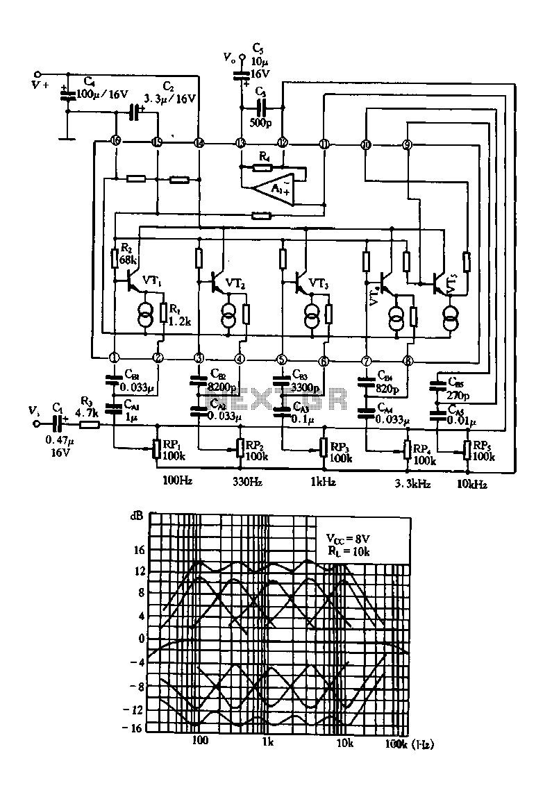
Figure 1-99 illustrates a five-band equalizer circuit utilizing the TA7796 integrated circuit. This circuit is designed for public electricity voltage amplification and includes analog inductors integrated with transistors. The circuit features a common voltage operational amplifier (op-amp), with VTs...

Basic features include an internal 512k-bit EEPROM, allowing for continuous recording and playback at any time, with long-term retention of voice data after power loss. The voice recording time is 20 seconds, and it supports segmented recording and playback....
A voice sound recording circuit is desired, which, when triggered, will play the recorded sound through an amplifier circuit. The proposed voice sound recording circuit can be designed using a microcontroller or dedicated audio recording ICs, along with an amplifier...