
Inductivity Meter Using IC 555

The inductance meter designed in this project utilizes the IC 555 timer in astable mode to generate a square wave signal. The frequency of this square wave is influenced by the inductance of the coil being measured, as well as the associated resistor and capacitor values in the circuit.
The basic configuration involves connecting the inductor in series with a known resistor and capacitor. The output frequency from the IC 555 is monitored, typically using a frequency counter or a microcontroller, which can translate the frequency into an inductance value based on the known values of the resistor and capacitor.
A transistor is employed in this circuit to amplify the output signal from the IC 555, ensuring that the frequency can be accurately measured even at low inductance values. The choice of transistor should be appropriate for the frequency range and the expected output load.
Resistors are used to set the timing characteristics of the IC 555, while capacitors are critical for determining the oscillation frequency. The design must ensure that the capacitor used has a suitable tolerance and temperature coefficient to maintain accuracy in measurements.
Overall, this inductance meter project serves as a practical application of basic electronics principles, demonstrating the use of common components to create a functional measuring device. The simplicity and low cost make it accessible for educational purposes and hobbyist experimentation.The aim of the project is to build simple low cost inductance meter. The main parts of the project are IC 555, Transistor, resistor and capacitor.. 🔗 External reference
Related Circuits
This easy electronic buzzer circuit is built based on a timer that operates to generate frequency. The IC timer NE555 is used as an astable multivibrator operating at approximately 1 kHz, producing a sound when powered on. The sound...
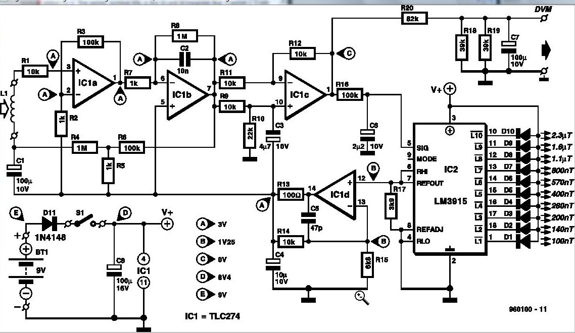
Some experts believe that static magnetic fields (SMFs) may affect the physical well-being of individuals. If one subscribes to this viewpoint, the magnetic-field meter described here will aid in locating sources of SMFs and assessing their strength. These results...
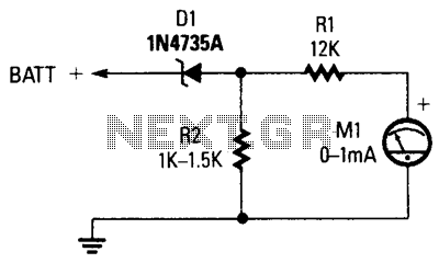
The circuit comprises a 0-1 mA meter (M1), a 6.2 V zener diode (D1), and a 12 kΩ, 1% resistor (R1). A load resistor (R2) is included in the circuit for the zener diode, with a non-critical value ranging...
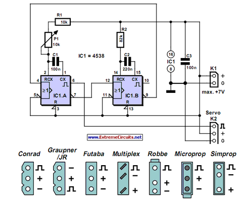
Individuals who frequently work with servos are likely familiar with situations where a servo tester is beneficial. The primary function of a servo tester is to produce a pulsing signal with a variable positive pulse width ranging from 1...
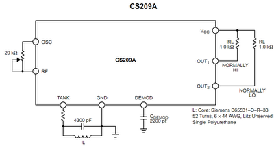
The operation principle of the proposed metal detector circuit is straightforward yet intriguing. The detection function is activated by sensing a decrease in the quality factor (Q) of the LC network associated with the circuit when a metal object...
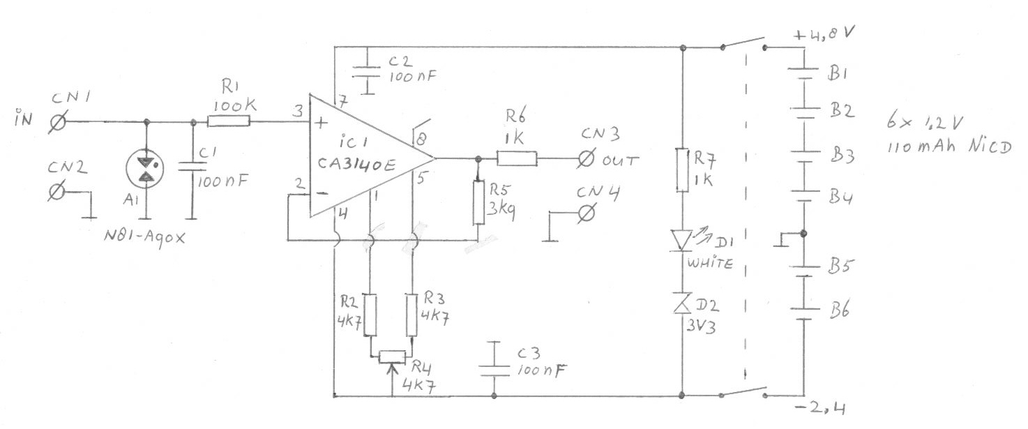
Another cause of voltage drift is the input current of IC1, which slowly charges capacitor C1. This effect is particularly noticeable when the output voltage is approximately 0 volts. The circuit in question involves an integrated circuit (IC1) whose input...