
inductor Cutting an RL Circuit

In this circuit configuration, the voltage source provides a continuous supply of electrical energy, which is dissipated through the resistor and stored in the inductor as magnetic energy. The energy stored in the inductor is a function of its inductance (L) and the voltage (V) across it, divided by the resistance (R) in the circuit.
Upon interruption of the circuit by cutting the wire, the inductor reacts to the sudden change in current. Inductors inherently oppose changes in current due to their stored magnetic energy. When the circuit is broken, the inductor will attempt to maintain the current flow by inducing a voltage across its terminals, which can lead to a phenomenon known as back EMF (Electromotive Force).
This induced voltage can be quite high, depending on the rate of change of current and the inductance value. If the circuit is simply cut, the energy stored in the inductor may result in a high-voltage spike, which can potentially damage components or create an electrical arc across the cut wire.
To safely dissipate this energy, a snubber circuit or a flyback diode can be implemented. A snubber circuit typically consists of a resistor and capacitor in series across the inductor, which absorbs the energy and prevents voltage spikes. A flyback diode placed in parallel with the inductor allows the current to recirculate through the inductor, providing a path for the energy to dissipate safely.
In summary, cutting the wire in a circuit with a voltage source, resistor, and inductor leads to the release of stored energy from the inductor, which can cause high voltage spikes. Proper circuit protection measures should be employed to manage this energy safely.Say you have a Vsource Resistor and Inductor all nicely in a loop. You let the voltage source run until everything reaches a happy steady state. The Inductor should have energy (1/2)L*(V2/R2). Now. what happens if I cut the wire Where does the energy go 🔗 External reference
Related Circuits
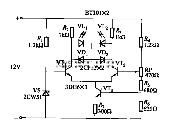
The circuit for monitoring DC power supply under-voltage and over-voltage is depicted in Figure 13-93. It is designed to ensure that the DC power supply voltage remains within normal operating limits. When the supply voltage is at 12V, the...
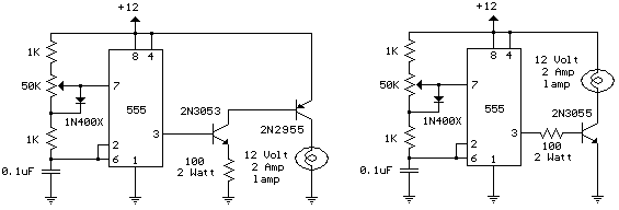
The schematic diagram illustrates a 12 Volt Car Lamp Dimmer Circuit Design utilizing a 555 Timer. This circuit can be employed to dim a standard 25-watt lamp. The 12 Volt Car Lamp Dimmer Circuit utilizes a 555 Timer in astable...
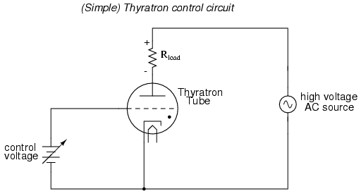
An often neglected area of study in modern electronics is that of tubes, more precisely known as vacuum tubes or electron tubes. Almost completely overshadowed by semiconductor, or "solid-state" components in most modern applications, tube technology once dominated electronic...
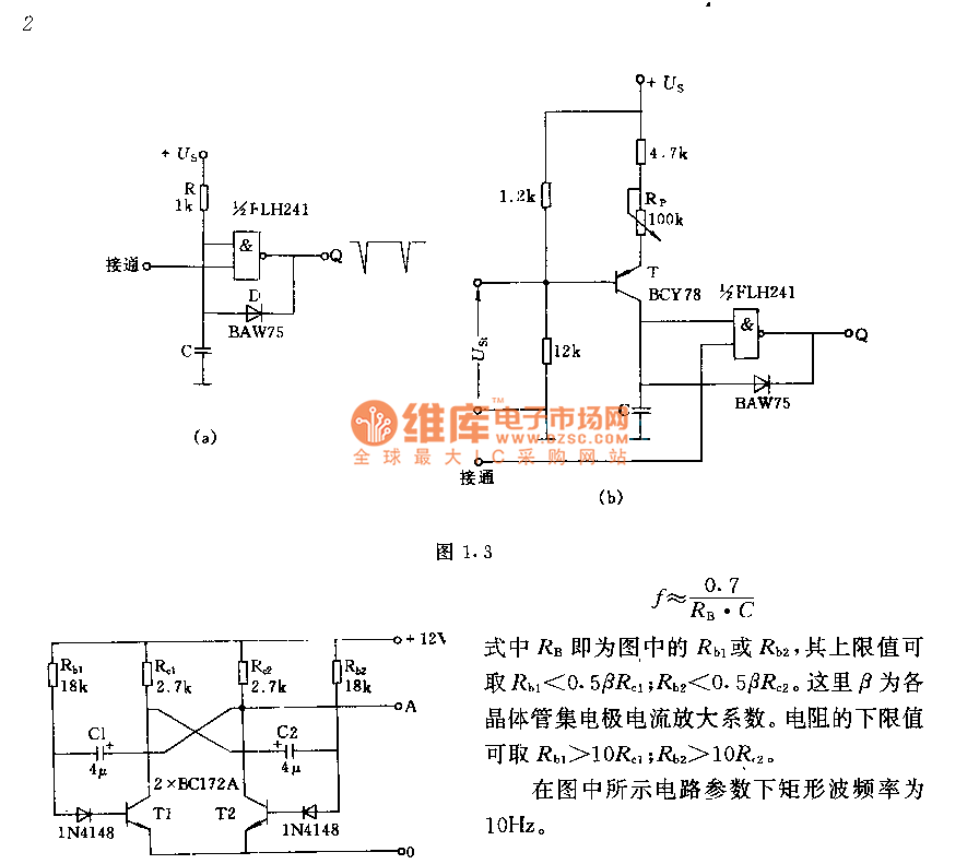
The circuit consists of two components whose parameters and models are designed to simultaneously generate a rectangular wave with a duty cycle of 1:1. The frequency is defined by the equation f = 0.7/(RB * C), where RB refers...
This circuit resembles an LED clock but utilizes 12 neon indicator lamps in place of LEDs. It operates on two high-capacity nickel-cadmium cells (2.5 volts), providing power for several weeks. A small switching power supply generates the high voltage...
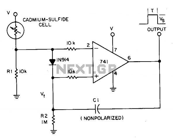
A photocell circuit provides automatic threshold adjustment. Monostable action prevents undesired retriggering of the output. With only one op amp IC, the circuit offers automatic adjustment of its trigger level to accommodate various light sources, changes in ambient light,...