
DC supply voltage circuit indicates one of the more limited

The DC power supply voltage monitoring circuit is essential for applications where maintaining a stable voltage is critical for the operation of connected devices. The circuit utilizes a voltage divider to sample the input voltage, which is then compared against predefined thresholds using a comparator.
When the supply voltage is at the nominal value of 12V, the voltage divider's output is stable, resulting in both LEDs being off. This indicates that the voltage levels are acceptable. The green LED serves as an under-voltage indicator, and its activation at 11.9V signals that the supply voltage has dropped below the acceptable limit. This is critical for alerting users to potential issues that could affect device performance or safety.
On the other hand, the red LED functions as an over-voltage indicator, lighting up when the voltage exceeds 12.1V. This feature is crucial for preventing damage to sensitive electronic components that may be connected to the power supply. The circuit can be integrated into various systems requiring voltage monitoring, such as power management systems, battery chargers, and industrial equipment.
In summary, this monitoring circuit provides a simple yet effective means of ensuring that the DC power supply operates within safe voltage limits, utilizing visual indicators to alert users to any deviations from normal operation.DC power supply under-voltage, over-voltage indicator circuit shown in Figure 13-93, use it to monitor the DC power supply voltage is normal. When the supply voltage is 12V, ad just RP, the sampling voltage of 6V. Two light-emitting diodes are not bright. When the power supply down to 11. 9V, the green LED lights VLz; when the supply voltage exceeds 12.1V, the red LED lights VLi.
Related Circuits

The bridge is a low-frequency push-pull power amplifier circuit with a simple structure, capable of delivering an output power of up to 1W. It can be utilized as an external amplifier for devices such as Walkmans, phones, doorbells, alarms,...
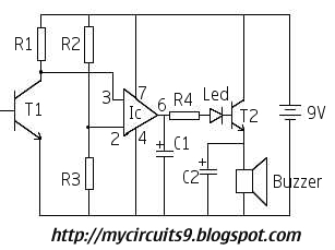
This circuit activates an alarm whenever an object crosses the laser beam emitted by a laser. The output of the IC TL071 goes high when the laser beam is interrupted. This output voltage is further amplified by an NPN...
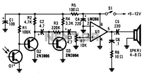
This receiver for amplitude-modulated light signals utilizes a phototransistor Q1 mounted within a parabolic reflector to enhance its range. Any NPN phototransistor is suitable for this application. An emitter-follower configuration using Q2 drives an amplifier stage Q3. The output...
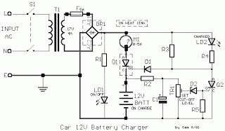
All car batteries require a 12V battery charger, which also applies to marine, RV, and power sports batteries. The high-efficiency lead-acid batteries available today necessitate more effective charging techniques. The battery charger is a crucial tool for prolonging battery...
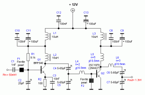
The RF power amplifier circuit described here utilizes the transistors 2SC1970 and 2N4427. This FM RF amplifier operates within the frequency range of 88-108 MHz, delivering an output power of approximately 1.3W from an input driver of 30-50mW. The...

A switching power supply with an output voltage significantly lower than its input voltage exhibits an interesting characteristic: the current drawn by the supply is less than its output current. However, the input power (UI) is, of course, greater...