
Inexpensive frequency counter-tachometer

The ICM7555 is a low-power variant of the classic 555 timer, known for its efficiency and versatility in timing applications. In this configuration, the astable multivibrator mode allows continuous pulse generation, which is essential for creating the gating signal required for the operation of the circuit. The duty cycle and frequency of the output can be adjusted by varying the resistances Ra and Rb, which are connected to the timing capacitor. The 5 MΩ potentiometer serves as a coarse adjustment, allowing for significant changes in the frequency, while the 1 kΩ potentiometer enables fine-tuning for precise control over the output waveform.
The CD40106B is a Schmitt trigger inverter that can be configured as a monostable multivibrator. This component is crucial for generating a stable output pulse in response to a triggering event, such as a button press or a signal from another part of the circuit. The reset time delay feature allows for a controlled period during which the output remains inactive after being triggered, ensuring that the circuit can reset properly before the next operation.
In summary, this circuit effectively combines the ICM7555 timer and CD40106B components to create a robust timing and control system capable of generating precise gating and reset signals. The careful selection of potentiometers for calibration enhances the flexibility and accuracy of the circuit's performance, making it suitable for various applications that require reliable timing and signal generation.This circuit uses the low power ICM7555 (CMOS 555) to generate the gating, STORE and RESET signals. To provide the gating signal, the timer is configured as an astable multivibrator. The system is calibrated by using a 5 M potentiometer for Ra as a coarse control and a 1 jk potentiometer for Rb as a fine control CD40106B"s are used as a monostable multivibrator and reset time delay.
Related Circuits
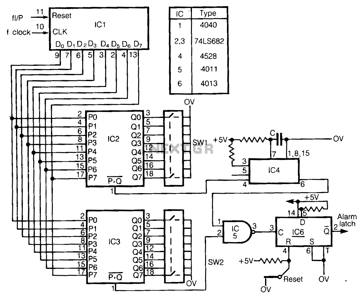
This circuit detects frequency variations that exceed preset limits. IC1 functions as a binary counter connected to the clock frequency (FcLK). The outputs from IC1 are compared with preset values set by IC2 and IC3. The input signal, which...
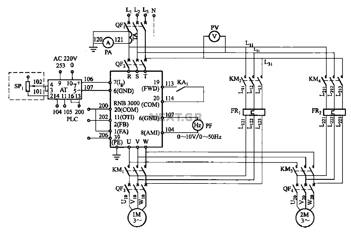
A control circuit for two motors, specifically for frequency control in a constant pressure water supply system, is illustrated in Figure 5-23. The circuit includes fault output terminals labeled 1 and 2, analog feedback current input terminals labeled 6...
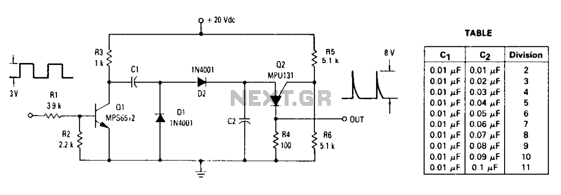
The ratio of capacitors C1 and C2 determines the division. With a positive pulse applied to the base of Q1, assume that C1 = C2 and that C1 and C2 are discharged. When Q1 turns off, both C1 and...
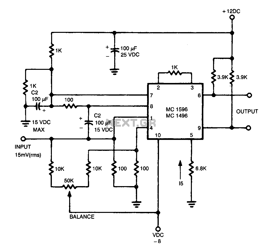
The output contains the sum component, which is twice the frequency of the input, since both input signals are of the same frequency. In a circuit design context, the described output suggests the presence of a frequency doubling mechanism, commonly...
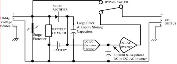
Thomas Edison developed the incandescent light bulb, which operated from a 110-volt DC source. The primary drawback of DC power was that it could only be distributed over short distances without needing to be regenerated. In the early 1900s,...
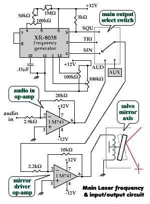
The aim of this project is to visually demonstrate the interactions of frequencies with one another. By utilizing mirrors and magnets to reflect a laser beam, a visual representation of the mathematical principles inherent in electronics is created. The...