
XR-8038 precision frequency generator
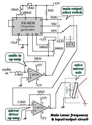
The electronic schematic for this project consists of several critical components, including the XR-8038 precision frequency generator, which serves as the heart of the system. The frequency generator outputs sine, triangle, and square waveforms that are essential for driving the magnetic scanners. Each scanner, either electromagnetic or permanent magnet type, is connected to the output of the frequency generators, allowing for precise control of the mirror positions.
The mirrors are strategically placed to reflect a laser beam that is directed at them, creating visual patterns on a projection surface. The use of potentiometers for tuning various parameters ensures that the system can generate a wide range of frequencies and wave shapes. The careful arrangement of resistors and capacitors in conjunction with the frequency generator allows for fine-tuning of the output, ensuring that the desired patterns are accurately produced.
The overall design emphasizes modularity, allowing for easy replication of the axis control systems. By ensuring that each armature operates independently, the project can create complex visual patterns that change dynamically based on the input frequencies. This project not only serves as an artistic endeavor but also as a practical application of electronic principles, demonstrating the intricate relationship between mathematics and visual representation in the realm of electronics.The purpose of this project is to visually communicate the effects that frequencies have with each other. By expressing these frequencies into mirrors and magnets that have a laser beam shining across creates a visual representation of that electronics is about; math in motion.
We wanted to have as much control of the math and add a little eye can dy. The most common outputs are Lissajous in nature. A harmonic SIN wave `jous of equal frequencies produce a perfect circle. When you start multiplying and dividing frequencies on either of the two axies, bends and twists occur. Strange patterns evolve as various attributes to the respective wave shapes are altered. Many times these changes seemingly create 3 dimensional images. Streching it over the time it takes for the image to be produced one may say that creates a Z, or time, axis as well.
These `wireframe` images are mathematical in nature so it may qualify as being Fractillian in nature. This is speculated becuase of the presence of `knots` in the overall image. A `knot` is a point or area in which the most mathematical changes happen. Or it could be defined as a stationary point or area where a visual radiance is sourced from. We accomplish this by using an ac signal (a frequency) controlling the horizontal and vertical sweep of a pair of magnetic salvos.
These salvos (also called scanners or x/y plotters) are equiped with mirrors that move with the corrosponding frequency (or audio) signal. Projecting a laser beam into the mirrors creates Lissajous and Quaderature patterns across the room and onto the wall.
Any frequency sourse can be used to drive these mirror sets, including audio. Interesting patterns can be generated with music controlling both axies. How about a steady frequency controlling horizontal movement and audio for the vertical It can be done with this device. Two seperate laser emmiting armatures were constructed. Each with it`s own pair of frequency generators that controlled each axis. Each armature shared a different type of salvo design. The smaller of the two used an electromagnetic style salvo. They have their own +12, ground and input leads. The main laser uses a permanent magnet type salvo that works just like a speaker coil, only the magnet is on it`s side and the coil pivots on an axis.
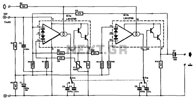
Then a signal is applied to either of these salvos, a `wobble` occures with the mirrors and the projected beam. First off, I`m only going to give half the story as it pertains to one of the two axisies. If you get this half to work for one waveshape, just build a copy for the other axis. It`s that simple. anyway, here`s the flow-chart. An XR-8038 precision frequency generator is used because of it`s simple hookup and output lines. These IC`s are a straight up and hassle-free. We wanted as much control of the waveshapes as possible. We can adjust the frequency, duty cycle, and wave shape symetry to SIN, Triangle and Square wave outputs.
Some adjustments are more prevelant with various shapes and others may have no effect (this is normal). To calculate the freq. range desited do not use the standard 1/(2piRC)! Use the formula 0. 15/(RC) instead. Potentiometers come in standard ranges, so pick your upper frequency roll-off point and calculate C. The R of the calculation is across pins 4 and 5. To obtain our duty cycle, a 5k Pot was placed across pins 4 and 5 so that the center tap connects to I think a 1M pot.
This acts as a voltage divider causing a voltage unballance between 4 and 5. The larger pot that controls frequency is connected as a voltage divider. One pin and the center tap going to Vcc +12v and the last pin going the the duty cycle center tap. If you need a fine tuner, add a smaller pot of about 50K ohms. If you do, don`t forget to recalculate your value of C. To get wave shape symetry, two 100k ohm pots are used. They are center tapped and voltage divided between +Vcc 12v and Ground. These cente 🔗 External reference
Related Circuits
Free domains and hosting with up to 1GB of disk space, unlimited transfer, and access to PHP as well as 5 MySQL databases. The maximum size of a single file is not limited. This service offers a robust web hosting...
The function generator features two BNC outputs: one for the high speed [1 to 8 MHz] square signal (BNC1) and another for the DDS signal (BNC2). Offset and amplitude can be regulated by two potentiometers: offset in range of...
The electromagnetic RBI timer features a simple structure, is cost-effective, and is commonly utilized in high school physics experiments. However, a significant drawback of the electromagnetic RBI timer is the substantial errors it produces during experiments. This issue arises...
Input values for R1, R2, and C, then press the calculate button to determine the positive time interval (T1) and negative time interval (T2). For instance, using a 10K resistor (R1) and a 100K resistor (R2) along with a...
The frequency of this sine-wave oscillator is determined by a direct voltage, U, ranging from 0 to 15 V. The distortion in output signals of up to 10 Vpp does not exceed 1%. When the output is reduced using...
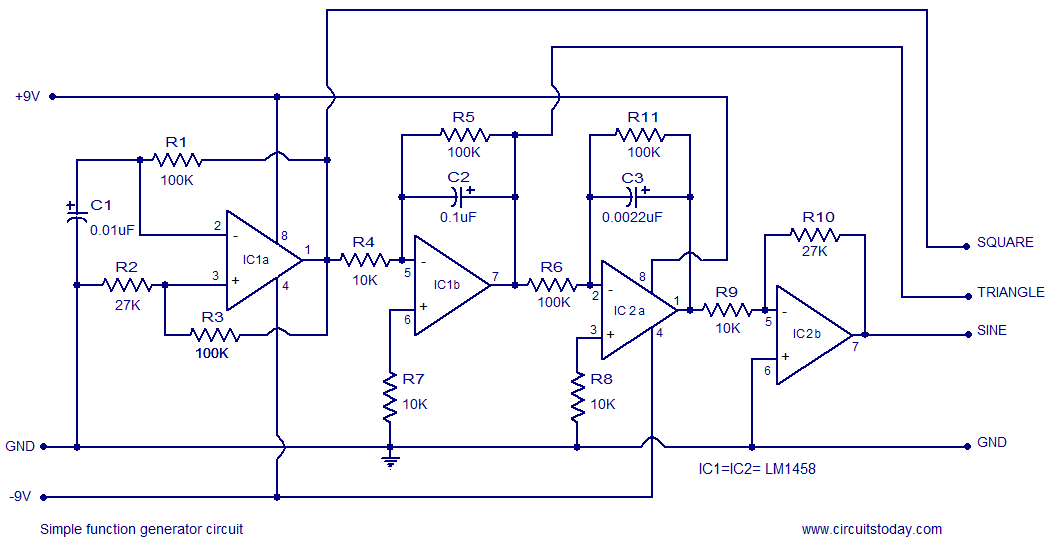
A simple function generator circuit utilizing the LM1458 is presented here. The LM1458 is a dual general-purpose operational amplifier. The two op-amps within the LM1458 share a common bias network and power supply line, yet operate independently. The function generator...