
Infra-Red Remote Control Tester

This infrared light tester circuit is a practical tool for evaluating the performance of remote control devices. The core component, the Schmitt trigger gate IC1f, is configured to amplify the weak signals received from the IRED, which serves as the sensor capable of detecting IR light. The choice of the LD274 diode is crucial, as it is sensitive to the specific wavelengths emitted by typical remote controls.
The R-C network, formed by capacitor C1 and resistor R2, plays a vital role in shaping the output signal. It ensures that the output LED, D2, does not remain continuously illuminated when exposed to steady IR sources, such as sunlight or artificial lighting. Instead, the circuit is designed to respond to pulse bursts, which are characteristic of remote control signals. This design allows for a clear indication of whether a remote control is functioning correctly, as the LED will light up momentarily in response to valid IR signals.
The sensitivity of the circuit is optimized to detect IR signals from distances of up to 50 cm, making it suitable for general testing applications. The low power consumption of the circuit, drawing less than 1 mA during operation and virtually no current in the absence of IR light, enhances its usability. This efficiency means that the tester can remain in a ready state without the need for manual power management, such as an on/off switch.
The compact design of the circuit allows it to be enclosed in a small ABS case, which provides protection and portability. The construction drawing serves as a guide for assembling the components securely within the enclosure, ensuring ease of use and accessibility for anyone needing to test remote control devices. Overall, this circuit is a valuable addition to the toolkit of anyone working with infrared remote controls, providing a quick and reliable method for performance verification.This little circuit is invaluable for quick go/no-go testing of just about any remote control transmitting infra-red (IR) light. The tester is battery-powered, built from just a handful of commonly available and inexpensive parts, and fits in a compact enclosure.
Schmitt trigger gate IC1f is used as a quasi-analogue amplifier with, unusually, an i nfra-red emitting diode (IRED) type LD274 acting as the sensor element. An R-C network, C1-R2, is used at the output of the gate because all IR remote controls transmit pulse bursts, and to prevent the output LED, D2, lighting constantly when day-light or another continuous source of IR light is detected. This creates a useful quick test` option: point the tester at direct daylight, and the indicator LED should light briefly.
The sensitivity of the tester is such that IR light from remote control is detected at a distance of up to 50 cm. The circuit is designed for very low power consumption, drawing less than 1 mA from the battery when IR light is detected, and practically no current when no light is detected.
Hence no on/off switch is required. The construction drawing shows how the tester may be cased` using a small ABS case from Conrad. 🔗 External reference
Related Circuits
The following circuit illustrates a stepper motor controller. This circuit is based on the PIC16F84A integrated circuit. Features: a transistor is utilized to drive the motor. The stepper motor controller circuit employs the PIC16F84A microcontroller, which serves as the central...
This circuit is constructed using standard components and can be easily adapted for computer control. By utilizing inexpensive surplus transistors and a stepper motor, the overall cost of the circuit can be maintained at under $10. The described circuit is a...
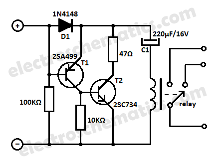
This low current relay circuit is designed for use in battery-operated electronic devices. Its operating current is in microamperes (µA). This is achieved by using a bistable relay and incorporating additional components to enable the relay to function like...
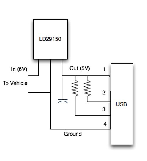
How can a 1950 Studebaker be enhanced? By installing an iPod Nano in the dashboard. The team at MAYA Design created a touch-controlled sound system for this project, referred to as the "Nano-Baker" or "Stude-iPod," utilizing a pair of...
PWM rectifier power controller power supply. Visit the page to read the explanation about the associated circuit diagram. A PWM (Pulse Width Modulation) rectifier power controller is a sophisticated electronic circuit designed to convert alternating current (AC) to direct current...
The concept for this crystal tester circuit originated from the necessity to evaluate a large quantity of oscillator crystals that were not in use within a hobby box. Testing each crystal individually without the proper equipment would have been...