
Infrared Fire-Cracker Igniter

The described circuit utilizes a remote control ignition system for firecrackers, enhancing safety by allowing the operator to maintain a safe distance during detonation. The core components include an infrared receiver (TSOP1738), a monostable multivibrator (IC1), and a relay (RL1) to control the high current required to ignite the firecracker. The circuit is designed to be powered by a 12V battery, providing a reliable power source while ensuring the system remains portable.
The use of a monostable multivibrator allows for a timed output that ensures the relay remains activated long enough to heat the heater element (R7) to ignition temperature. The choice of a heater element with a resistance of 3 to 3.5 ohms ensures that sufficient current flows through it to generate the necessary heat. The circuit's design prioritizes safety, as the metallic enclosure protects against accidental ignition and ensures durability against the harsh conditions of firecracker use.
The IR receiver is strategically positioned to receive signals from the remote control, allowing for user-friendly operation. The inclusion of LEDs serves dual purposes: they provide visual feedback on the circuit's status and indicate when the firecracker is about to detonate, thereby alerting the user to retreat to a safe distance.
For optimal performance, it is essential to select components that can withstand the electrical demands of the circuit. The relay must be rated for at least 5 amperes to handle the current flowing through the heater element, and the wiring should be appropriately gauged to prevent overheating. The entire system should be tested thoroughly to ensure reliability and safety before actual use.Firecrackers are normally ignited by using a matchstick or a candle. You have to run away quickly after igniting the fuse of the firecracker. This method of igniting firecracker is unsafe, because the danger of the firecracker bursting before you reach a safe distance is always there. The device described here uses remote control, usually used wit h TV receivers or CD players, to burst the fire-cracker. Thus the firecracker can be ignited from a safe distance using the circuit described below in conjunction with the remote control. In the diagram shown here, normally the output of IC1 is low and green LED2 is on` and the red LED3 off.
` This indicates that the circuit is ready for use. When any key on the remote control is pressed, output pin 3 of IRX1 (IR receiver module TSOP1738) goes low. This output is connected to pin 2 of IC1 via LED1 and resistor R4 to trigger the monostable operation of IC1.
The output of IC1 remains high for a period equal to 1. 1G—R2G—C2. With the values of the components given in the circuit diagram here, the period works out to 3. 5 seconds approximately. This activates relay RL1 and red LED3 glows and green LED2 turns off. On` state of red LED3 indicates that the firecracker is about to burst. R7 is a small part of the element of an electric heater (220V, 1000W), which is kept away from the electronic circuit and connected to the relay contacts through a thick electric cable. The resistance value of short length of the heater element (R7) is 3 to 3. 5 ohms. A current of around 4 amperes flows through it when connected to a 12V battery. Flow of 4A current through R7 for 3. 5 seconds makes it red hot, which ignites the fire-cracker. The circuit is powered by a 12V, 7AH battery. IC2 provides about 9V for the operation of the circuit. The circuit should be housed in a metallic cabinet to prevent it from being damaged by bursting of the firecracker.
The IR receiver and the two LEDs should be fixed on the front panel of the cabinet. Wiring and relay used in the circuit should be chosen such that they are able to carry more than 5 amperes of current. 🔗 External reference
Related Circuits
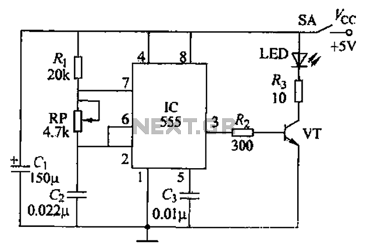
The circuit utilizes a 555 timer integrated circuit along with a transistor (VT) and several external components to create a multivibrator circuit. The charge and discharge time constants, Ti and T2, are defined, where Ti is approximately 0.7 times...

This page presents information on infrared - Across The Track train detection circuits. The circuits are designed around the LM339 comparator chip and can use a wide assortment of matched infrared - emitter / detector pairs. The infrared "Across The...

The circuit consists of Q1, a phototransistor that responds to an intensity of amplitude-modulated infrared light source, and a three-stage, high-gain audio amplifier. Transformer T1 is utilized to match the output impedance of the receiver to modern low-impedance (low-Z)...
The DTMF codec stands for dual-tone multi-frequency codec. The multiple-channel infrared remote control switch circuit that incorporates the DTMF is depicted in the figure. It consists of an infrared remote control signal emitter, an infrared receiving signal amplifier, a...
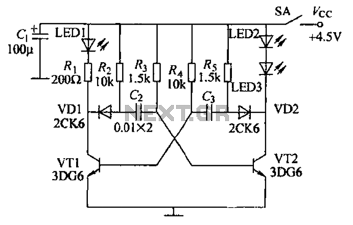
Transistors VT1, VT2, and associated RC components are configured to form a multivibrator. The multivibrator operates with resistors Ra and R4 serving as base bias resistors for VT2 and VT1, respectively. When the switch SA is closed after applying...
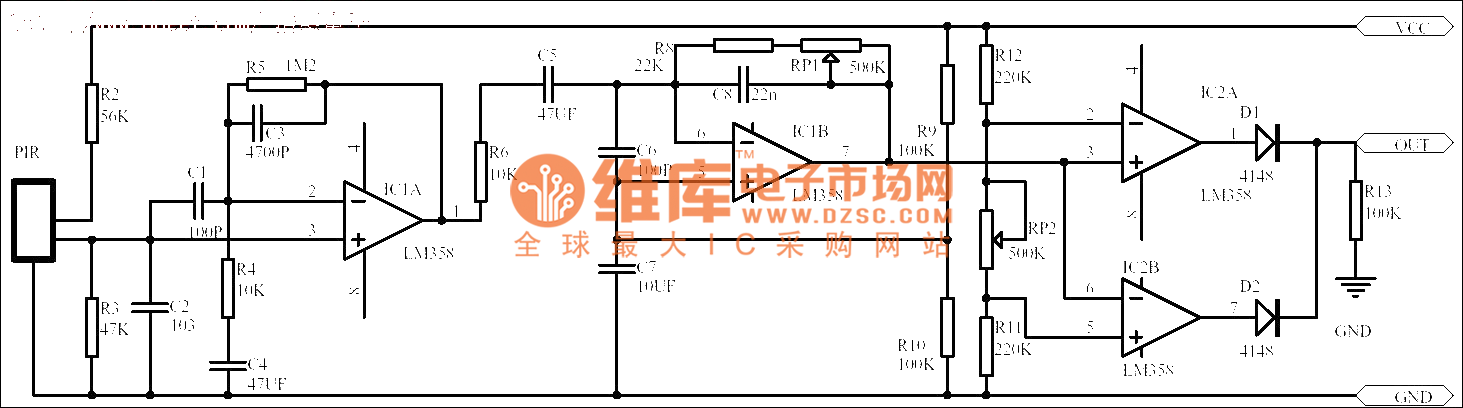
Passive human body infrared sensor circuits are generally similar in design, although some may have fewer stages. The circuit illustrated is sourced from the NICERA manufacturer and is considered a classic example. The front-end stage consists of a low-frequency...