
Modern Homodyne reciever circuit

The modern homodyne receiver is a sophisticated device designed to process various types of radio frequency signals, specifically Amplitude Modulated (AM), Continuous Wave (CW), and Single Sideband (SSB) transmissions. The circuit typically consists of several key components, including an RF input stage, a local oscillator, a mixer, an intermediate frequency (IF) stage, and a demodulator.
The RF input stage is responsible for capturing incoming signals from the antenna. It often includes a bandpass filter to ensure that only signals within the desired frequency range are allowed to pass through, minimizing interference from unwanted signals.
The local oscillator generates a signal at a specific frequency that is mixed with the incoming RF signal. This mixing process occurs in the mixer stage, where the two signals combine to produce sum and difference frequencies. The desired output is typically the difference frequency, which corresponds to the intermediate frequency (IF) used for further processing.
The IF stage amplifies the mixed signal, which is then filtered to remove any unwanted frequencies, ensuring that only the desired signal is passed on to the next stage. This amplification is crucial for improving the signal-to-noise ratio, allowing for better performance in receiving weak signals.
Finally, the demodulator extracts the original information from the modulated carrier wave. For AM signals, this involves envelope detection, while SSB signals require more complex processing techniques, such as coherent detection or phase-locked loops, to accurately recover the transmitted audio or data.
Overall, the modern homodyne receiver's design allows for efficient and versatile reception of various modulation schemes, making it a valuable tool in communications and radio technology.This is the complete circuit of the modern homodyne receiver. This receiver can receive AM CW and SSB transmissions. 🔗 External reference
Related Circuits
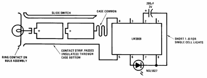
The schematic presented below illustrates the Flashlight Finder circuit diagram utilizing the LM3909, a monolithic oscillator specifically designed for flashing Light Emitting Diodes (LEDs). The Flashlight Finder circuit employs the LM3909 integrated circuit, which is capable of generating a series...
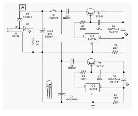
This easy-to-construct "Handy Pen Torch" electronic circuit has a low component count and utilizes two power white LEDs for lighting. It operates on a low voltage supply of 4.8V DC. The Handy Pen Torch circuit is designed to provide a...
This circuit illustrates a 2W RF amplifier based on the M/A-Com LF2810A MOSFET. The transistor is rated for 10 watts at 28 volts. The 2W RF amplifier circuit utilizing the M/A-Com LF2810A MOSFET is designed to amplify radio frequency signals...
VOX is a voice-controlled switch commonly used for microphones, serving as a replacement for the traditional switching button. The actuating threshold is adjusted through the volume potentiometer. The VOX (Voice Operated Switch) circuit functions by detecting sound levels and activating...

RTD sensors are measured using a precision 24-bit analog-to-digital converter (A/D) that includes a built-in programmable gain amplifier. The connections for 2-wire, 3-wire, and 4-wire RTDs are illustrated. This setup facilitates the connection and measurement of RTDs with amplifiers and...
An even power device is designed to supply energy to a computer. It is typically intended for converting alternating current (AC) into low-voltage direct current (DC). Without this component, a computer is merely a collection of metal and plastic...