
Input switching circuit

The described circuit involves a relay that operates based on a closed circuit condition within a digital logic framework. The relay serves as an electromechanical switch that can control a larger load, such as motors or lamps, based on a low-power input signal.
In this configuration, a touch input switching circuit is integrated, allowing users to activate the relay through a simple touch interface. The touch input can be implemented using capacitive or resistive touch sensors, which detect the presence of a finger and send a signal to the digital logic circuit.
The digital logic circuit processes the input from the touch sensor and determines whether to energize the relay coil. When the relay coil is energized, it closes its contacts, thereby completing the circuit for the larger load. Conversely, when the touch input is released or if the circuit is opened, the relay deactivates, opening the contacts and disconnecting the load.
This design can be utilized in various applications, including home automation systems, where touch-sensitive controls provide an intuitive interface for managing electrical devices. The relay's ability to isolate the control circuit from the load circuit enhances safety and allows for the integration of different voltage levels.
Overall, the combination of a relay with a touch input switching circuit provides a versatile solution for controlling electrical devices in a user-friendly manner.Is a relay controlled by a closed turn the digital logic circuit Rd touch input switching circuit.
Related Circuits
This circuit is designed to indicate when room noise exceeds a predetermined threshold, utilizing a flashing LED to signal this condition. Three fixed noise levels are selectable: 50 dB, 70 dB, and 85 dB. The circuit employs two operational...
There are two types of solar automatic tracking controllers. One type utilizes a Schmitt trigger light control, which consists of a light sensor and a Schmitt trigger or monostable trigger. The second type employs two light sensors and two...
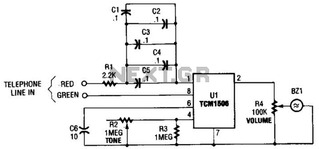
The circuit utilizes the TCM1506 ring detector/driver integrated circuit, which is a monolithic IC designed to replace mechanical bells in telephones. It is powered and activated by the telephone line's ringing signal, which ranges from 40 to 150 V...
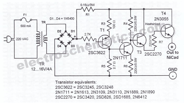
This NiCd battery charger circuit schematic can charge 6 volts as well as 12 volts NiCad batteries. It uses a transformer that can deliver 4 to 5 A current. The NiCd battery charger circuit is designed to accommodate both 6V...
This electronic lie detector circuit project will provide two readings: one for challenging questions posed to the subject and another to indicate their emotional state. The electronic lie detector circuit operates on the principles of galvanic skin response (GSR) and...
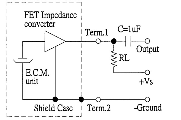
The back of the electret microphone resembles the drawings of the CUI Inc part number CMA-4544PF-W, which will be included in the parts kit. While debugging the data logger software on Windows, an oscilloscope practice lab was conducted using...