
interafce 16x2 lcd with avr

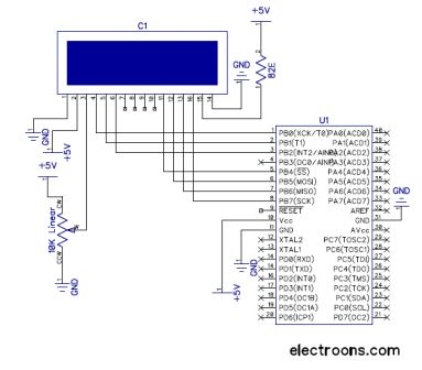
The interfacing of an ATmega16 microcontroller with a 16x2 LCD involves several key components and configurations that facilitate the display of characters. The 16x2 LCD consists of two rows, each capable of displaying 16 characters, and operates using a parallel communication protocol.
In this setup, the microcontroller communicates with the LCD in 8-bit mode, which allows for the transmission of data in 8-bit chunks. The data pins of the LCD are connected to Port A of the ATmega16, which is configured as an output port. This configuration enables the microcontroller to send character data directly to the LCD for display. The specific data pins are typically labeled D0 through D7, corresponding to the 8-bit data format.
Control signals are crucial for proper operation, and they are managed through Port B of the ATmega16. The control pins include:
- RS (Register Select): This pin determines whether the data being sent is command or character data. When RS is low, the microcontroller sends a command; when high, it sends data.
- R/W (Read/Write): This pin indicates the direction of data flow. When low, the microcontroller writes data to the LCD; when high, it reads data from the LCD.
- EN (Enable): This pin is used to latch the data into the LCD. A rising edge on this pin signals the LCD to read the data present on the data pins.
The initialization sequence of the LCD is critical for ensuring proper functionality. This typically involves configuring the LCD to operate in 8-bit mode, setting the number of display lines, and enabling the display. After initialization, the microcontroller can send characters to be displayed by writing to the appropriate data and control pins in a timed sequence.
In summary, the interfacing of an ATmega16 microcontroller with a 16x2 LCD in 8-bit mode involves connecting the data pins to Port A and the control pins to Port B, ensuring proper signal management for effective character display. This setup is fundamental in various applications, including embedded systems and user interfaces.LCD comes in various configurations and the most popular one is 16x2 matrix display. This article shows the interfacing of ATmega16 with LCD by displaying a simple character on the LCD. In this project LCD is working in 8-bit mode i. e. , the data transferred to the LCD must be in 8-bit data form. The PortA of ATmega16 is connected to data pins of LCD and is defined as LCD_DATA. PortB is defined as control pins (Rs, R/W and En). 🔗 External reference
Related Circuits
The RW line is the "Read/Write" control line. When RW is low (0), the information on the data bus is being written to the LCD. When RW is high (1), the program is effectively querying (or reading) the LCD....
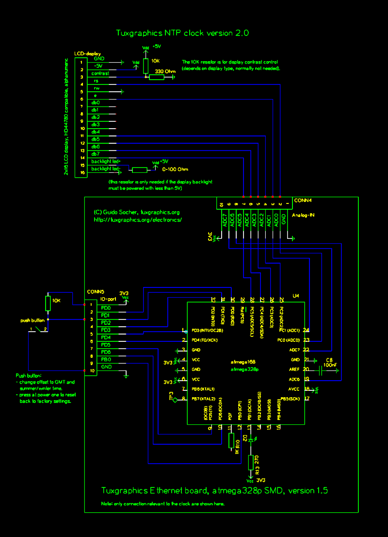
The Network Time Protocol (NTP) has transformed global timekeeping, enabling accurate date and time retrieval from anywhere in the world. NTP is a straightforward UDP-based protocol that can be implemented in microcontrollers. The Tuxgraphics NTP clock has gained popularity...
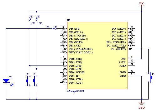
A demonstration of external interrupts in the AVR (Atmega8) microcontroller, including a circuit diagram and C code for the interrupt service routine (ISR). The Atmega8 microcontroller is a versatile device widely used in embedded systems, particularly for applications requiring external...
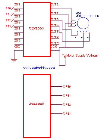
This tutorial utilizes the ATmega8 microcontroller with a 4 MHz crystal oscillator and unipolar stepper motors. The ULN2003, a Darlington pair driver integrated circuit, is employed for motor control. The ATmega8 microcontroller is a versatile 8-bit device from the AVR...
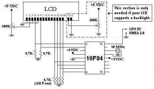
This is a project that I started back late 2003 when I just starting to learn PIC programming. I wanted to building something that actually did something useful. This project is based on a PIC16F84. I actually came up...
This circuit is designed to program AVR controllers such as the AT90S1200 using a parallel port. The circuit is straightforward, with IC1 serving as a buffer for the signals transmitted between the parallel port and the microcontroller. This encompasses...